System 80 and the Expansion Unit - Images (Outside and Inside)
The various System 80 models referred to in the text below are described in full on the System 80 Models page. Here you get close up and personal with a couple of them. The two units on display represent either end of the System 80 timeline. The first is an original MK I model. The second machine is a Blue Label model. These pictures reveal the innards of both, showing the major changes in hardware that occurred. The images can be matched up with the circuit diagrams and schematics from the Technical Manual reproduced on this page. Also included are the two versions of the Expansion Unit, described in the Expansion Options page.
Clicking on the images of naked or semi-naked boards will give you a larger, more detailed view.
System 80 Mark I (version 1)
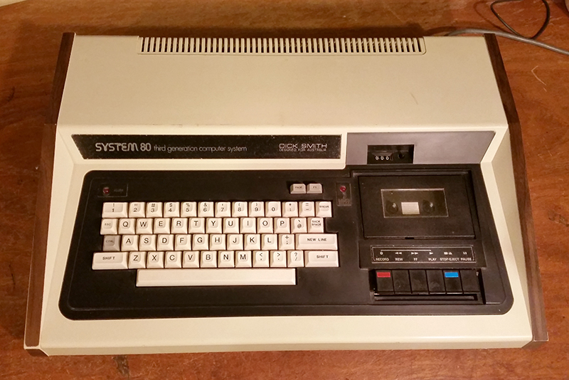
Figure 1a. The original Dick System 80 (MK I (version 1))

Figure 1b. System 80 (MK I, version 1) - The view with the cover off
Here you can see the self-contained power supply unit in the right hand corner, the cassette recorder and full-stroke keyboard sitting atop two circuit boards. Note the spaces for extra keys at the top of the keyboard mount. Some hobbyists took advantage of these and added keys in after-market modifications.The CPU board is on the left-hand side and the video interface card on the right hand side. These boards are connected to each other with two very stiff ribbon cables.

Figure 1b. System 80 (MK I, version 1) - fully naked
Here you can see both boards exposed. Note the eight 4116 RAM chips giving a total onboard memory of 16k. Also note the four ROM chips. This is not typical. Normally only three of these 4k ROM ICs would be fitted to MK 1 models. The forth IC is a 2k utility EPROM which, along with its socket, has been fitted by a previous owner.

Figure 1c. System 80 (MK I, version 1) - Video Interface Card
The VRAM consist of seven socketed 2102 chips. Models with this video interface card (the MKI v1 and MKI v2a) were only capable of uppercase, although third-party lower case mods were available. These consisted of another 2102 chip (to give full 8-bit wide video memory) and a replacement character generator.

Figure 1d. System 80 (MK I, version 1) - CPU Board
Note the large heat sink attached to the power transistor. With a large case and plenty of ventilation slots, the System 80 machines seldom had issues with overheating.
System 80 - Blue Label
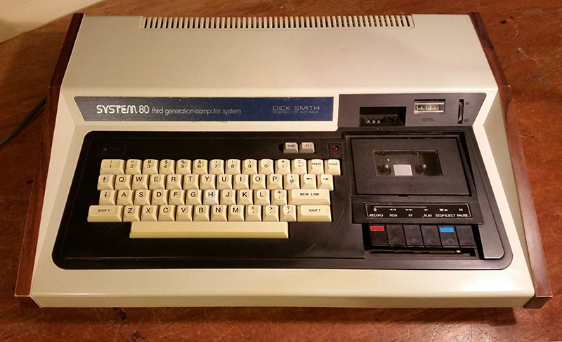
Figure 2a. The Dick System 80 (Blue Label)
Refinements to the MKI saw two other "Black-Label" variants (versions 2a and 2b), which (among other things) introduced a volume control and level meter to the cassette deck and introduced more keys. Eventually all were superceded by the Blue Label model which had a full complement of keys in a similar arrangement to the original TRS-80 Model 1.

Figure 2a. The Dick System 80 (Blue Label) - Video Interface Card
Internally, the biggest change between the early MKI models (MKI version 1 and version 2a) and the later ones (MKI version 2b and Blue Label) was on the video interface card. In this board, the seven 2102 VRAM chips have been replaced by two 2114 ICs and there is a new character generator. With full 8-bit video memory, lower case is now standard. These newer boards are easy to recognise as the character generator has a vertical orientation from the circuit board's front edge rather than horizontal. The interface cards differ slightly between the MK1 version 2b and Blue Label in that the latter has some minor modifications to the cassette circuitry to accommodate feeding sound to a speaker.

Figure 2b. The Dick System 80 (Blue Label) - CPU Board
The CPU board remained much the same in all models, although later models such as the MK II and Blue Label had a 2k ROM EPROM and socket fitted as standard. The particular Blue Label unit shown here has had its factory-fitted 16k RAM expanded internally to 48k via the RAM piggyback method. This was a common after-market modification.

Figure 2b. The bottom of my Dick System 80 (Blue Label)
Designed for Australia it says but that's a Dick Smith marketing ploy of course. Also designed for Europe, and many other places. Note the copyright notice for the BASIC Interpreter from Microsoft, which shows that 12k of the ROM at least was entirely legal.
Expansion Unit version 1 (X4010)
The first version of the expansion unit was essentially a three-slot S100 backplane and PSU housed in a sturdy plain nondescript white case. The case was strong enough to support the weight of a monitor. Card edge connectors on the front of the expansion unit (moving left to right) were for disk drives, the computer expansion bus and parallel printer (Figure 3). The mainboard (Figures 4a and 4b) was plugged into the top slot (Figure 5) of the backplane and housed the disk controller, parallel printer port and RS-232 port.

Figure 3. X4010 Expansion unit showing the card edge connectors

Figure 4a. X4010 mainboard angled view

Figure 4b. X4010 mainboard top view

Figure 5. S100 backplane slots
Absent from Figure 5 is the RAM card, which was usually included in one of the two remaining slots. The RS-232 DB connector was located on the top rear right-hand side of the case, plugged into the mainboard via cables.(Figure 6a and 6b).

Figure 6a. RS-232 DB connector on the rigfht-hand side of the case

Figure 6b. RS-232 connection from the mainboard to the case
Expansion Unit version 2 (X4020)

Figure 7a. Card edge connectors at the front of the X4020 Expansion Unit case
The case did not change much in the second version but the order of the card connectors was different reflecting a change on the mainboard. The leftmost connection was now for the computer bus (hence lining up the connecting cable with the computer better) while the next two card edges were for disk drives and the printer respectively.

Figure 7b. X4020 Expansion Unit mainboard
More significantly, gone was the S100 backplane. Instead there was a single board (Figure 7b) which now held up to 48k of RAM but did not include the RS-232 interface. The latter could be purchased as an extra and fitted to a 20 pin connecter on the underside of the board. The RAM sockets (minus their 4116 chips) can be seen on the left. There was also a 50-pin connector on the bottom of the board providing access to the system bus which could be used to connect an S100 interface board or custom hardware. You can see where these connectors are soldered on to the board on the top-middle left of the photo.