Mac SE resurrection. This time a Bridge too Far?
Defeat. None of us like it. It rankles and irritates, and makes us grumpy.
So why would I bother writing about a failed project in this blog?
I do so to show that things can't always be fixed easily and sometimes there comes a point when you feel a broken unit is just not worth the time and energy you are spending on it. However, there is a bright side to even attempting a repair. You usually learn something from it!
The Problem
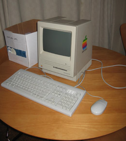 Photo
1. Attractive but inert Mac SE
Photo
1. Attractive but inert Mac SE
For about a year, the broken Mac SE has glowered at me from the spare parts pile.
I got this machine as a donation. On receipt it went intermittently for about 2 hours then gave up the ghost altogether. The drive spun but there was no bong and the screen stayed totally black. I pulled it to bits, retouched the solder on the analogue board then decided it was probably the flyback transformer. I really didn't need to do anything more with it. I had a perfectly good Mac SE/30 so I didn't NEED to repair this one.
However, I'd run out of things to fix! Secondly, I had a borrowed oscilloscope so maybe it was worth taking a second look. Finally, I now knew a lot more about electronics than I did when I first tinkered with it. Although I'd tentatively diagnosed the flyback transformer as the problem, I wanted to that make SURE that it was. If cheap easily-obtainable components were the cause I might even fix it!
The temptation was too much. I hauled the SE onto the workbench and cracked open the case.
Getting some documentation
My initial diagnosis had been the flyback transformer. After a quick look, this was still a strong hypothesis. There was a faint light in the neck of the tube so the CRT heaters were working. There were no cracked transistors, dry solder joints or leaky capacitors at least as far as I could see. However, I knew by now that looks can be deceptive.
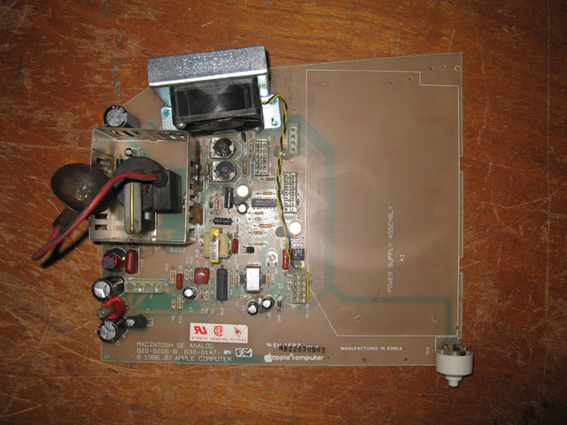
Photo 1. Analogue board for the Mac SE. Flyback lead has large rubber cup at end.
I had a useful guide which discussed common Baby Mac problems and how to fix them. I found that document when I first got this Mac. There were a number of possible causes of my symptom and I didn't want to replace everything. No, what I needed was a circuit diagram so I could find out what connected to what and where the current should go.
Wanting something and getting it is two different things. Eventually a fellow Kiwi pointed me to a document which contained a circuit diagrams of early Macs such as the Mac Plus. It didn't specifically cover the SE but apparently the SE analogue board is very similar to the Plus. It was at least something! Here it is, along with the accompanying text...
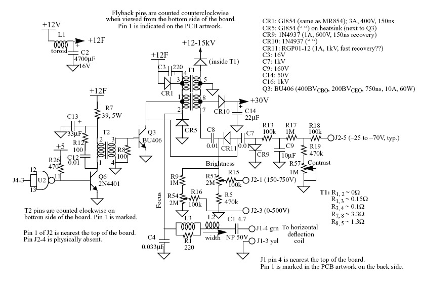
Figure 1. Circuit diagram of the Analogue Board
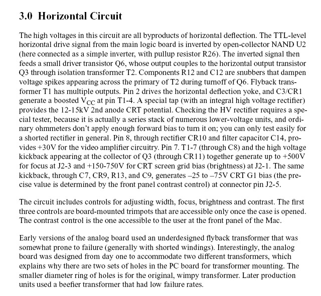
Figure 2. Text from that same document
The biggest problem with the circuit diagram was the parts used different identifiers to what was on the SE. For example on the circuit diagram the flyback transformer was called T1. One the Mac SE, this was called T2
Measurements
One way to diagnose a faulty unit is to have a good unit nearby to compare things with. My working SE/30 could fulfill this purpose. Armed with a volt meter I started taking measurements on the board, and comparing them to the same values on my working SE/30. This is what I found...
- Voltages on T1 pins 1-4 on the Mac SE were 12v
- Voltages on T1 pins 1-4 on the working SE/30 were 20v!
- Voltages on T1 pins 5-8 on the Mac SE are practically zero. No high voltages (hence a back screen)
- Voltages on T1 pins 5-8 on the working SE/30 were as indicated on the diagram (i.e. very high!)
In the description of the circuit it said ..”and C3/CR1 generated a boosted Vcc at pin T1 1-4”. I read that to mean that 12v is boosted to about 20v. Certainly on the working SE/30 there is 12v one side of the C3/CR1 and 20v on the other. In the broken SE there was NO boosted voltage.
Replacements
All the evidence pointed to the capacitor at C3, diode at CR1, transistor at Q3 or flyback transformer at T1. These are exactly the components suggested as being faulty by the initial repair guide (note: these are the identifiers used in the circuit diagram, not the SE board).
My chief suspect was the capacitor at C3 seen here on the right (C13 on the SE).
I replaced it.
No change.
Hmmm...then maybe the diode CR1 just beside the capacitor (CR3 on the SE board)? It seemed ok from testing but why not try it and see?
Still no change!
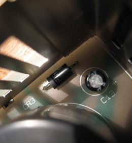
Ok. So how about the transistor at Q3 (shown below)?
![]() I
measured this for resistance across the base and emitter, then base and
collector and found some resistance both ways as expected. However it
was then pointed out to me that I really needed to desolder this from
the board otherwise the the current from the base will simply find its
way to the collector (earth) through the coil at T2 (Duh!).
I
measured this for resistance across the base and emitter, then base and
collector and found some resistance both ways as expected. However it
was then pointed out to me that I really needed to desolder this from
the board otherwise the the current from the base will simply find its
way to the collector (earth) through the coil at T2 (Duh!).
I extracted. Measurement post extraction showed base<--> emitter ok. About 500 ohms or so one way and infinite resistance when I swapped the probes. However, a check on the base<---> collector showed infinite resistance BOTH ways! This seemed unusual. I'd expected there to be about 500 ohms or so from the base to the collector.
I felt I had found the problem. I promptly ordered the part. When it arrived I tested it again for connectivity. Hmm...same result? This time I also tested between collector and emitter also and found about 500 ohms one way? I don't think I tested these pins with the first transistor (I can't recall now). I would have expected infinite resistance across those particular pins on both the original one and this replacement.
Now I was a little confused? I'd assumed this transistor was a bipolar one and collector--emitter junction should show no conduction in either direction. Maybe the middle leg (which I assumed to be the base) was actually the emitter and what I'd thought was the emitter was the base?
Perhaps the transistor hadn't been faulty after all?
Switch on
Anyway, this was the last throw of the dice. If this didn't work, it must be the flyback transformer. I soldered in the new component, wired everything back up to the analogue board and threw the switch!
Still nothing on the screen. I measured the voltages around the transistor on the board. They were the same as the measurements with the old transistor. In other words there was no change. A flyback transformer problem was looking very likely.
Suddenly something happened! The hum of the fan started to change tone. It started to slow down. Then, alarmingly, wafts of smoke started to appear!! Coming from where though? Hard to see ...maybe the power supply? Or perhaps further up the analogue board. Eventually the fan ground to a near-halt. I switched off.
Ok, so that didn’t go so well (-:
Re-examination
Checking the unit I discovered a few things.
![]() I’d
forgotten to plug the flyback lead, back onto the side of the screen (duh!).
That was a stupid mistake. There are lots of connectors on an SE, but
I shouldn't have forgotten that onel.
I’d
forgotten to plug the flyback lead, back onto the side of the screen (duh!).
That was a stupid mistake. There are lots of connectors on an SE, but
I shouldn't have forgotten that onel.
Looking closely at the transistor I found it had a crack in it (see opposite)?
This was either from it burning out (maybe this is where the smoke came from?), or possibly from over-tightening the screw which secures it to the Flyback cage.
Could be either.
Taking stock
So. The transistor had cracked and the power supply had failed. The former could have cracked because I over tightened it. Then again, perhaps it was because I didn’t plug the flyback into the screen? Who knows what the naked leads of the flyback were resting on when I turned on the machine? Did they cause a short or surge right through the computer. Maybe this is also why the power supply has failed.
Either way, I decided my adventure with this particular machine was over.
Reflections
I'm now of the opinion that the original fault was the flyback transformer, and the original transistor was probably ok. Flyback transformers are hard to come by and replace, so perhaps this unit was always doomed. I made a basic mistake not plugging the flyback screen lead back in after the transistor replacement, and this could have blown something in the power supply? Maybe the power supply was going to fail anyway? Perhaps I was just too heavy-handed, in screwing the transistor back in?
I don't really know the answers to these questions and I'm not motivated enough to find out.
I'm still mystified about the readings I got on the transistor. I must do some research and check if the BASE leg is always the middle one in these large flat power transistors. Either it's not in these, or they are not typical bipolar ones.
Perhaps the new transistor was faulty?
So lessons learned are:
- Always check all leads carefully to make sure they are plugged in. It’s easy to miss one where there are a few
- Large transistors with a screw hole at the top shouldn’t be screwed in too tightly (although this might not have been the cause of failure in this case)
- Check components when out of circuit or readings can mislead you (this is probably the most valuable lesson)
What now then for the SE?
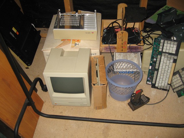
Photo 5. The Mac SE. Now back in the parts pile
The tube is a useful spare part, as it’s swappable with the other Macs. Cases can be used for aquariums of course (but I'm not really into fish). The SE logic board would make a good wall hanging!
Now that is a distinct possibility.
Tez
23rd April, 2009