Restoring a System 80 / Video Genie/ PMC-80 Part 1: Repairing a screen flicker issue
 Introduction
Just recently I've dragged out my three System 80s for some exercise. These workout sessions are also a good time to diagnosis and fix any outstanding issues such as this one. My showcase blue and black label 48k System 80s are now in perfect health.
My third unit is a 16k black label model. It's a little tatty on the outside and I've always considered it a parts-machine. Originally it was 48k in capacity and when I received it it wasn't going at all. I checked it out and discovered a faulty 4116 RAM chip. Being short of 4116 chips, and needing a few for my other machines, I removed most of the RAM hence downgrading this unit to 16k. The machine then booted up and worked. It still wasn't free of issues though. Given this was suppose to be a parts machine, I really should not be worried about restoring it, but I just can't help myself. I'd like to get this machine back to a useable (and perhaps salable) condition.
The problem
The issue was with screen refresh. Whenever this happened, horizontal white lines would flick on and off. When the screen was refreshing a lot, such as in Meteor Mission seen below (Figure 1) these lines would always be there, flicking on an off several times a second and always in different places.

Figure 1. Screen symptom in Meteor Mission
Now the System 80 (and TRS-80 Model 1) always did flicker a little during these machine language games. However, the lines were normally black and there weren't quite so many of them! Something was definitely screwy in the video circuitry somewhere.
When the screen was not refreshing it was fine and all characters including the graphic ones looked normal.
What the forums said
I wondered if anyone else had come across this before and would know what it was just by seeing it. Consequently I sought advice from the Vintage Computer Forums, EACA Google group and other discussion groups. Some very helpful replies poured in. A couple of folks identified the 74SL74 at Z40 and the 74LS175 at Z3 or the circuitry between them as possible candidates for the fault. Z40 generates a blanking pulse during CPU read/writes to the video RAM and Z3 clears it. I thought I'd pursue this line of inquiry.
What I did
A quick check of the board showed nothing amiss. I felt the best approach would be just to replace the 74SL74 chip at Z40 and see what happened? I'm quite used to clipping off small logic chips and extracting the pins from the board now, so I figured it wouldn't take me too long. I removed the IC by clipping it off it's legs. I then checked a replacement IC by piggybacking it over the legs of the old IC, which were still embedded in the board. No change. Bugger! Well, it obviously wasn't the Z40 chip. I did the same for the Z3 chip (Figure 2). Still no change. Damn!
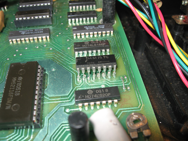
Photo 2. A replacement IC for Z3 tested by piggybacking over the legs of the original
Oh well, I figured I might as well solder sockets in and populate them with the replacement ICs while I contemplated my next move. I removed the video board entirely, removed the pins and started to add the sockets.
Something suspicious
I worked on the Z3 first. No issues there. However when I was inserting the socket into the Z40 slot I suddenly noticed something. A track had been cut close to the IC (figure 3). I hadn't noticed this before (Duh!). It was now so obvious I couldn't believe I'd missed it!

Figure 3. Cut track coming from pin 3 of the 74SL74 (Z40)
I checked the circuit diagram. That track came from pin 4 on the 74SL74 IC and it should not be cut. It should join onto a pin on the 157 IC beside it?! Maybe this was the problem? This computer had been hacked about in the past; that much was obvious. There was the odd bits of solder left on the legs of ICs and a few bridge wires connecting tracks that had been cut. It was like some modification (hi res graphics board?) had been installed at one stage then removed and the computer wired back to the way it was. Could the previous owner have missed a step and forgotten to join up this track?
Fixed!
At this stage, the cautious approach would have been to trace the signal on the circuit diagram, find out exactly what the gates in the associated ICs did and determine the implications of closing that break. However, I was very confident it was the result of a modification which was no longer there. I threw caution to the wind, soldered a bridge from pin 4 to the pad beyond the break (figure 4) and fired up the machine.
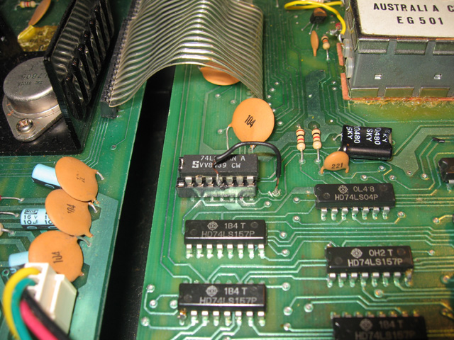
Figure 4. Jumper wire spanning the break
Success!! No more white lines. Diagnosis and repair accomplished!
Reflections
Had I taken more time I would have seen that track break. I SHOULD have seen it so. Especially when it was obvious the board had already been tampered with. The lesson is to spend a long time scrutinising a board before whipping soldered ICs out.

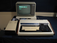
Figure 5. 16K System 80 with stringy floppy and syspand unit playing flicker-free lunar lander
Anyway, it's fixed now. However that is not the only issue for this machine. The previous owner has modified the cassette circuitry so that the second cassette (#-2) is the primary one. Not a bad idea considering the (low-) quality of the inbuilt tape recorders. However, when playing a game with sound (like Lunar Lander below) the inbuilt cassette relay switch clicks like mad! Something is not right there. I'm surprised I didn't notice the symptom on Meteor Mission. However, I had booted that off a disk with the Model 1 expansion unit plugged in so maybe the existence of cassette #2 circuitry on the expansion unit had something to do with it?
Anyway, the cassette/sound issue is the next problem to be investigated (Note: This is now fixed, and is detailed in Part 2 ). I want to do something about the case too, which is in poor shape.
Tez
2nd July, 2010