Restoring a second Dick Smith System 80 Part 2: Cassette repair
Introduction
This is part 2 of a restoration project bringing a junk System 80 unit back to health. Part 1 of the project can be found here.
Having solved a memory issue it was time to turn my attention to the dicey tape deck. I felt I knew what the problem was. A System 80 I worked on a few months ago had the same kind of problem. Sometimes there was a signal, sometimes there was not. That was the exact same symptom here. Replacing a few key capacitors solved that problem and I was sure that would also be the fix here.
If only I knew what was in store...
A closer look at the tape player
Time to checkout the device that one reviewer described as "the most horrible tape recorder East of Aden!". After cutting through years of dust with a damp cloth I could see there was a little bit of corrosion on some of the mechanics but nothing serious. The motor seemed to work although, as with all the System 80 tape decks I've come across, it had problems dragging tapes along in rewind mode. It did fast forward with my 30-minute per side tape though, albeit a little sluggishly.
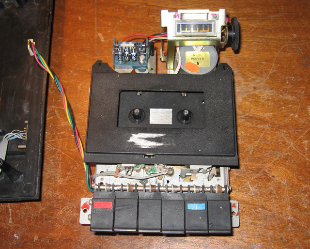
Figure 1. The subject of this blog
Capacitor replacement
Disassembling the tape player wasn't difficult. All the circuitry was there on a small board on the bottom attached by two screws. I soon had the three suspect electrolytic capacitors (C5, C7 and C9) out and replaced with brand new ones. Then it was a matter of re-assembling and testing.
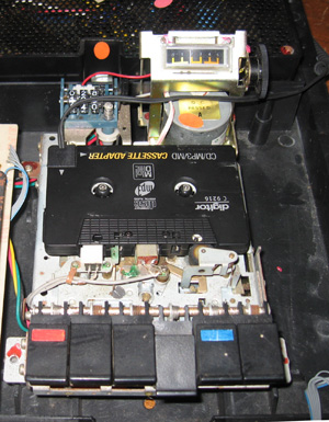
Figure 2. Using a cassette adaptor as a cassette
Testing setup
I had one tape with a game or two but not being able to rewind made using it a pain! It was then that another System 80 fan (Philip Lord aka nama) gave me an idea. Why not use one of those cassettes adaptors used for channeling MP3 player output through car audio systems? These devices were made for older cars (like mine) which had no MP3 facility in the audio setup. The idea was you could plug your MP3 player into this object that looked just like a cassette, then put the cassette in your cassette player. The audio was channelled into the car tape player's heads, and through the car amp and speakers.
As good fortune would have it, not only did my vintage vehicle have a cassette player as its only audio accessory, it also had one these tape adapter gadgets. I'd bought it to serve my iPOD. I'd never thought of using it as a data cassette substitute!
I took the cassette caddy off the System 80, positioned the mock cassette on the spindles (figure 2) and plugged its input into my audio card output. As I have a number of System 80/TRS 80 M1 programs on my PC as WAV files, this setup was ideal.
Using Window's built in sound recorder program I could rewind, fast forward, pause, play and alter the input volume all from my PC! As far as the System 80 was concerned, it was listening to a tape! Perfect!
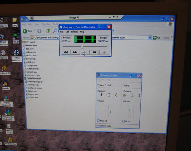
Figure 3. PC as a tape player
Disappointment and a puzzle?
So...having reassembled with three brand new capacitors installed I expected the testing to just be a formality.
Whaaatt???
The symptom was worse than before. Rather than a 50:50 chance of a signal, I was now down to about 25:75 against! Furthermore, there was often a huge "bump" at the start of loading where the meter needle would deflect at least half-way then fall to zero (and stay at zero!).
What the hell was going on?
I thought maybe the test regime was at fault so I reverted to loading programs off a standard cassette. Nope, same problem.
Hmmm.....ok, time for a coffee and a think.. Maybe this was a different problem than before, even though the symptom was similar. I carefully checked the circuit. Everything looked ok. I checked the power levels. They were normal. I figured the fault wasn't anything to do with the computer side of things. This was a load, and the level meter should show something coming off the heads even if the computer was ignoring it. If it was the meter that was broken, I still should get a load, or at least see an indication of a load (i.e. the "**") gleefully twinkling at me from the computer..
A friend Andrew Joll, knowledgeable in cassette circuits, suggested I disconnect the meter just in case its components were interfering with the process somehow. This I duly did. No change.
More component replacements
Maybe the LM324 quad op-amp was at fault? These ICs only cost $5 or so so why not replace it. I extracted the IC, put a socket in and added a replacement. No effect!
All the repair work in the last few years means I have picked up some skills in component extraction and replacement. I figured I had nothing to lose in replacing ALL capacitors, even though most seemed to have nothing to do with playback signal. After all they are cheap and available. They were replaced. No improvement!

Figure 4. Cassette board with almost everything replaced! Arrow shows new socketed quad op-amp
Ok, what was left. A few resistors, ceramic capacitors, a greencap and one transistor. Oh what the hell! I replaced the transistor. No difference.
Could it be a dried solder joint? I reflowed every joint of the underside of the board. That didn't help either!
By now I had an almost completely reconditioned board with mostly brand new components. The only originals left were the resistors, the ceramic caps and a green cap! These components don't usually fail without physical damage although it's not impossible. Resistors are fiddly things, and there were a number of them. I didn't feel motivated just to do a wholesale replacement of these passive components as it would be a real chore with no guarantee of success. Besides, I didn't have spares.
I decided to try a different tack.
Starting to trace the signal
Andrew Joll (cassette hardware guru) suggested tracing the signal and seeing if I could see it disappeared anywhere. I had Philip Avery's scope so I decided I'd attempt this, starting with the heads. I hadn't used a scope before for these tiny analogue signals but with some playing around I found the right settings. With the scope connected to the playback heads I could see a signal at 20Mv during play. It was a real signal as it flatlined when I stopped the audio feed from the PC. So there was nothing wrong with the playback head at least. It was reading and transmitting signals.
I then turned my attention to the LM324 quad op-amp IC to see what happened to the signal there. This is where my lack of knowledge ran me into a brick wall. According to Andrew above, the signal would be sitting on a DC bias of about 1/2 the rail value of 5V. Somehow I had to differentiate this voltage carrier from any tiny analogue signal on the scope. Problem was, I didn't know how? What settings did I use and was the scope even capable? Asking for help with this was the next obvious step.
About this time I thought about digging out one of my good System 80s (they are all packed away) and swapping its board with the unit under repair to make sure the fault WAS on the board. However, I rejected this. The problem MUST be on the board. The heads were ok and they went straight into the cassette circuit board!
Something suspicious
By this time I'd spent several nights and many hours on this cassette issue. Somewhat frustrated, I was flicking through the Dick Smith Technical Manual version 3 looking for inspiration when something caught my eye. In that edition of the manual there is a troubleshooting section. One part deals with cassette issues. I'd flicked over it before but hadn't digested the hints there in depth. It said all the usual things (dirty heads, misalignment etc) but the interesting part was at the end. Here is mentioned capacitors becoming dry and suggested if the user was experiencing loading difficulties, the 10uf capacitor at C7 should be replaced with a 47uf one.
The 10uf capacitor at C7??
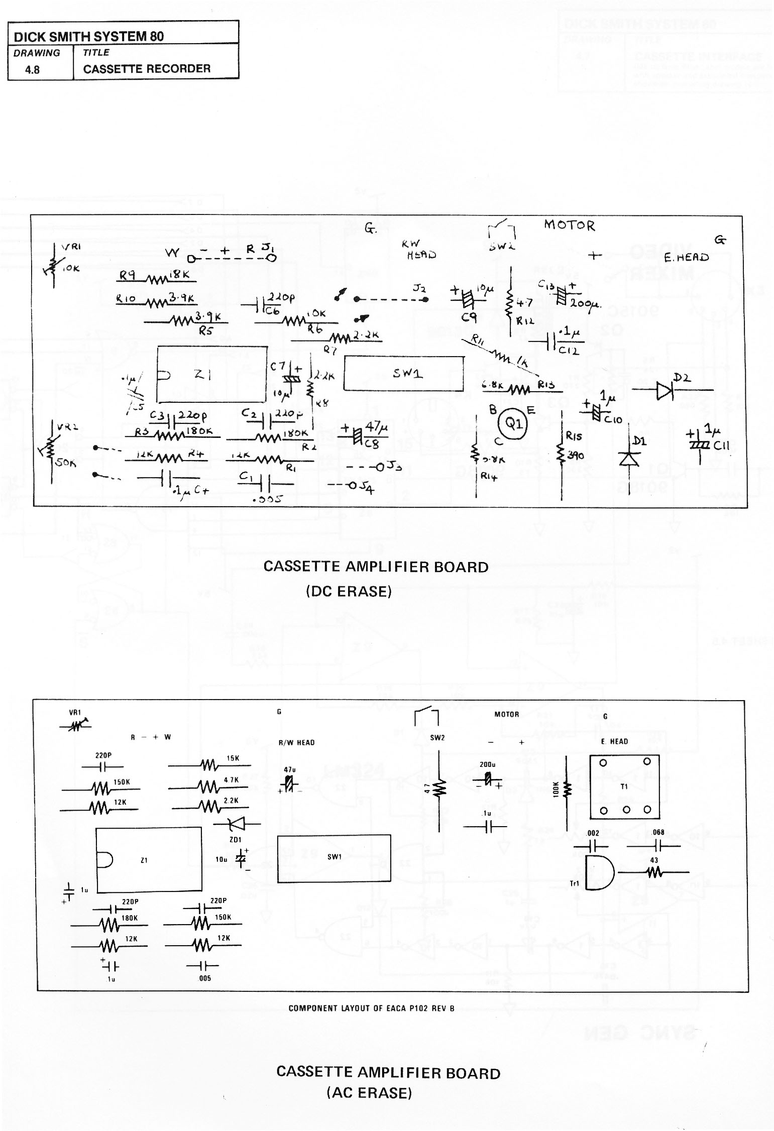
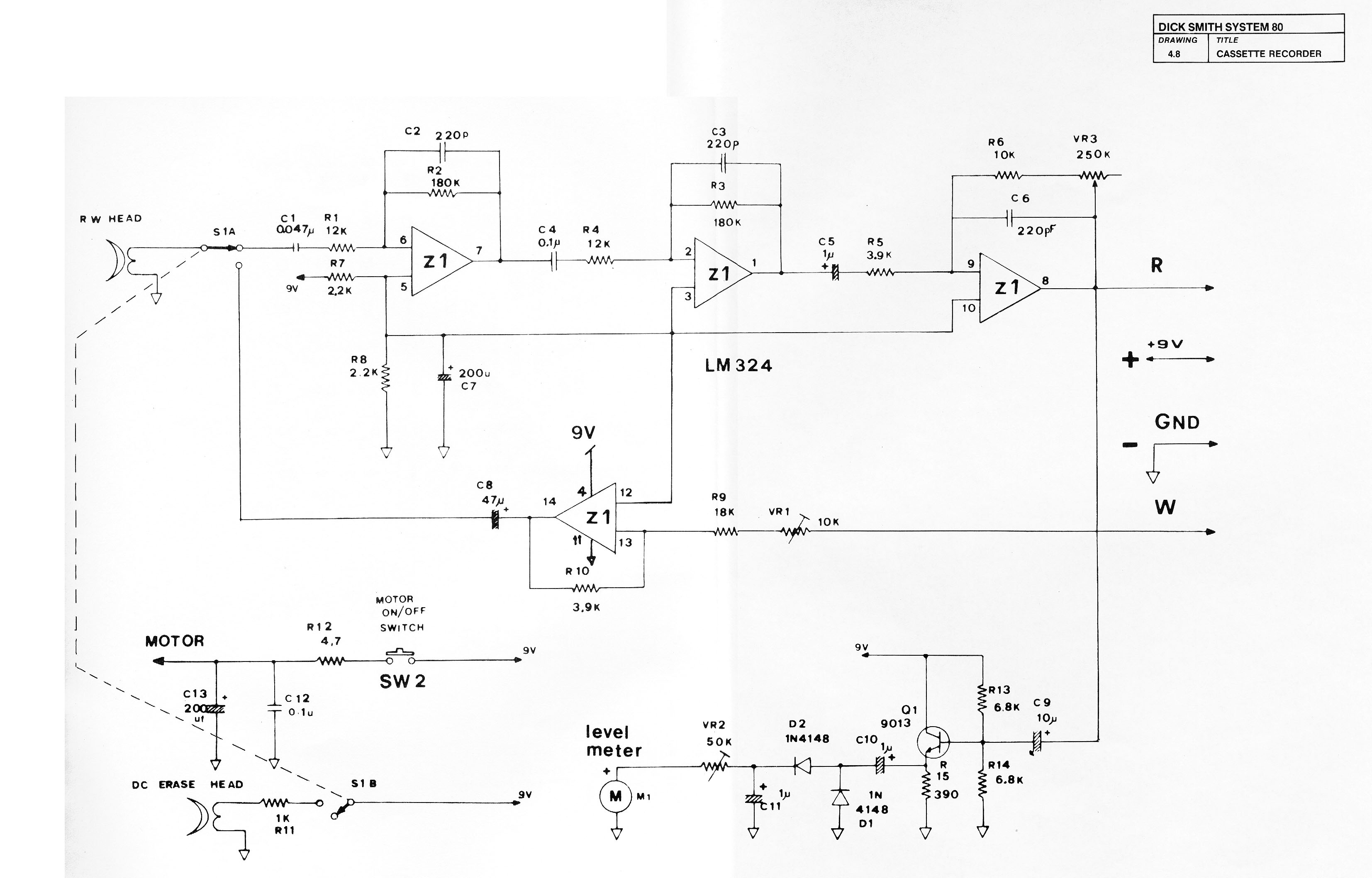
Now that statement seemed odd. The reason was that the circuit diagram labeled the capacitor at C7 as 200uf?? I did know that on the component layout diagram this was specified (faintly and roughly) as 10uf but I'd always considered that a case of mislabeling. In the manual the circuit diagram was larger, clearer and somehow seemed more authoritative. Besides (and more persuasively), the capacitor I had replaced at C7 was 200uf! However, seeing it written in a troubleshooting section of the THIRD (and last) edition of the manual made me think perhaps it was the circuit diagram that was wrong, not the component layout image!
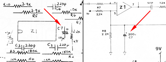
Figure 5. Diagrams with conflicting information
Success!
Anyway, with nothing to lose I replaced the C7 200uf capacitor with a 47uf one. Hmm...an improvement. Programs seem to load...mostly. There was still no signal sometimes but the ratio was now running 75:25 in favour of success.
My mood started to improve!
Being encouraged by this turn of events, I swapped the 47uf cap for a 10uf one. This time, although the volume seemed more sensitive, I got a consistent steady signal every time I loaded a new program! I loaded in a program 10 times in succession and it worked every time. There was no evidence of the large "bump" there had been before!
Could an erroneously labeled spec. in the circuit diagram been the problem all along??
Just as a final check I dragged out my "known-good" Blue Label System 80 out of it's box, opened it up and checked what the C7 capacitor rating was on that unit. Yes, you guessed it. 10uf!
Reflections
So. After all that, the cassette player is now fixed!
But is it? I still have nagging doubts. People more knowledgeable than me about electronics find it curious that higher capacitance at C7 (a decoupler) would cause such issues. It could be that there is a resistor or ceramic cap problem, which pushes things out of tolerance when 220uf cap is used at C7, but works within limits with the 10uf in there? I had fixed a cassette problem with one of my other units where I replaced that very cap..with a 220uf!
It remains a mystery *shrug*. Cassette loading works fine for now, but there is no guarantee the problem won't surface again. Anyway...

Figure 6. The System 80. Not quite there yet!
So. Time to bask in the satisfaction of a job well done? Well..err...no...
Having dealt with the memory problem and now having fixed the tape deck (as far as I can tell) the two issues I had originally identified had been put to bed. However, ANOTHER issue made its presence felt once I really started to work the machine. THAT diagnostic adventure is covered in Part 3.
Tez
30th September, 2010