Frustrating floppy controller fix in a Dick Smith System 80 X-4020 Expansion Unit
Introduction
This is part two of a two-part article describing how I resurrected a broken Dick Smith System 80 X-4020 expansion unit. Now having (at last) addressed the RAM problem, it was time to turn focus on the floppy disk controller.
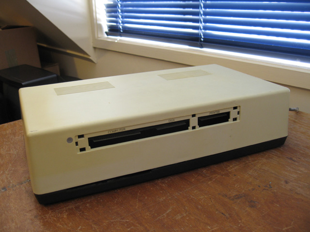
Figure 1. One of the haul X-4020s. RAM-enabled but with a faulty disk controller
The symptoms were simple. Drive 0 would just sit there spinning happily for its 10 seconds or so but that was it! In the words of Adventure-game writer Scott Adams, "Strange, nothing happened?". Although you could hear the stepper motor return to base sometimes, there seemed to be no attempt to seek. Something was broken.
Swapping the FD-1771 Chip
The IC that did most of the work regarding drives was the famous Western Digital FD-1771. I had two other expansion units whose drive controllers were fine, so I figured a good first step would be to swap over these large 40 pin chips to see if that was the problem. Hopefully not, as these ICs are hard to get.
I dropped in a FD-1771 from the working machine. Switching on revealed no difference. Hmmm....The problem lay somewhere in the circuitry itself. Oh well, that was good. A logic chip is easier to find than a FD-1771.
Did I say 40 pin earlier on? By the time I'd extracted the 1771s, one of them only have 38 left (opps)! This thing was wedged in tight, and even with care I couldn't stop it leaving a couple of its thin legs behind in the socket.
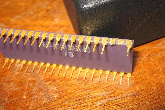
Figure 2. Opps! This extraction left a few bits and pieces behind
Luckily, it wasn't the whole of the pins. The stubs were still there, so I cut off a couple of legs from faulty junk ICs I fished from the bin and soldered these on. They took just fine, and the IC was back to its full complement.
Taking readings
Time to start testing. I didn't have a theory of operation description of the circuit but I did have a circuit diagram and information on how the the FD-1771 operates. I had Philip Avery's scope and a working X-4020 for comparison. I felt I was up to the challenge!
I tried to take a very logical approach to testing. I started by measuring things with the System 80 connected, recording what happened on IC pins both before, during and after a boot. I found a useful technique for this. I'd snap a photo of the scope display with a digital camera as I tested the pins of the broken unit. I could then go through the same with a working unit and compare what the camera had captured from the faulty one. The workbench was setup so it only took a few seconds to swap expansion units over.
The FD-1771
I started by looking at the pins of the FD-1771 chip.
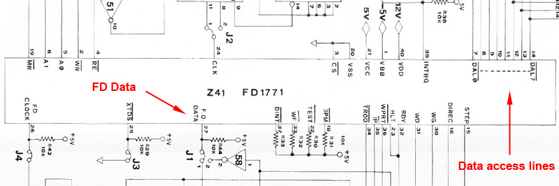
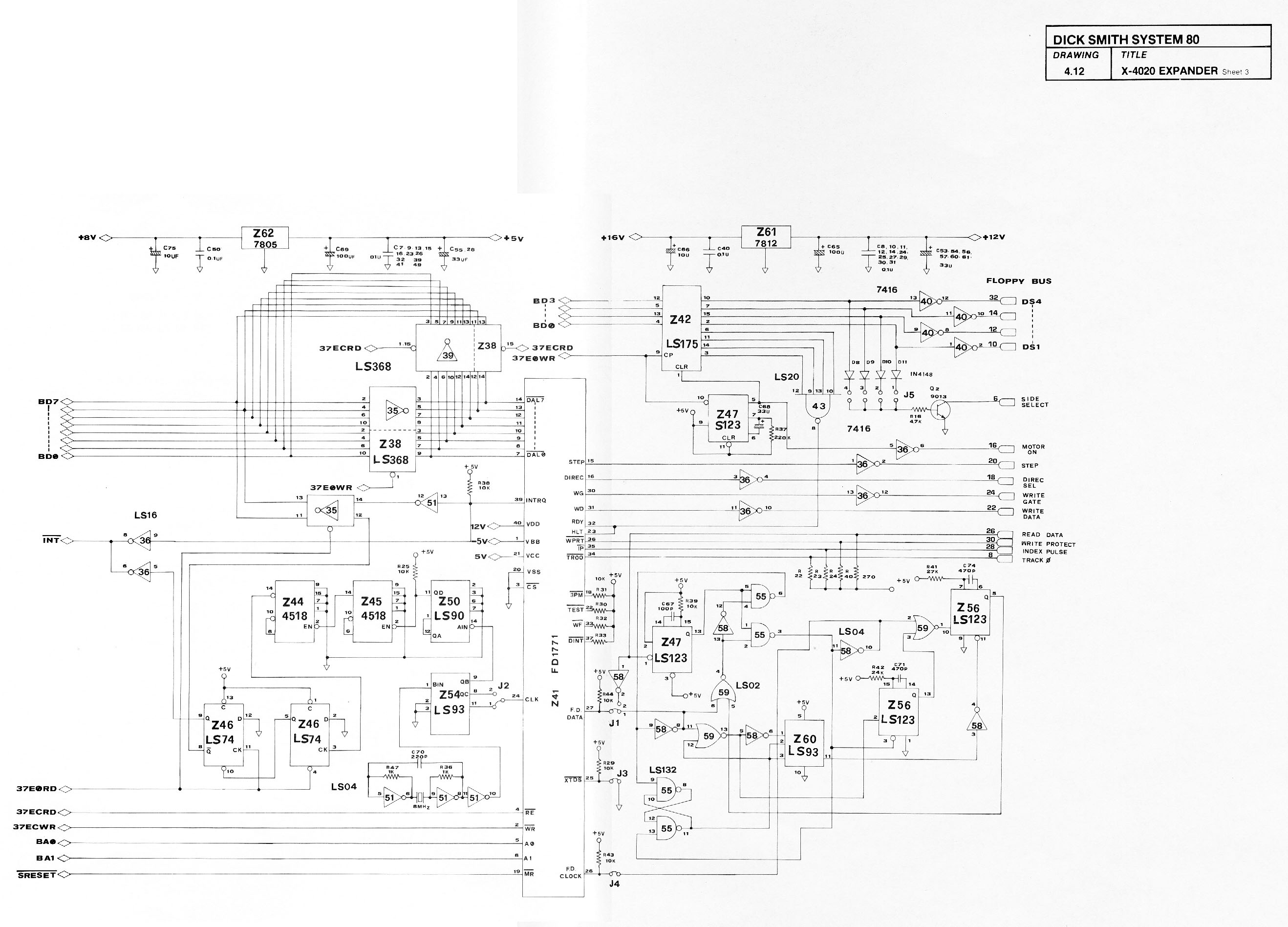
Figure 3. FD-1771 schematic
There was a difference in a couple of areas. First, the FD-data pin showed a difference not in the shape but in the frequency of the wave (Figure 3). The faulty unit was showing the wave on the right.
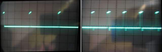
Figure 3. Wave differences on the FD-data pin (pin 27). Output from faulty unit is on the right.
Also the data access lines showed different patterns between the working and non-working X-4020s. These lines were Input<-->Output lines so I expected this would happen anyway, if data wasn't getting through off the disk in one of the units.
I decided to focus on the FD Data pin. This was an input pin only and the signal coming in differed between working and non-working units. I figured this must be a clue!
The input circuit.
Figure 4 shows the input circuit associate with this pin.

Figure 4. Input circuit for the FD Data pin
I started testing with the Read Data line from the connector edge then worked through all the logic ICs. At any minute, I was expecting see a stuck gate or an obvious wave difference.
Strangely, I didn't?? IC after IC was tested in the circuit, with every one giving similar results to the good unit. Eventually I'd tested every damn one!! No difference. And yet pin 27 of the FD-1771 was telling me there WAS a difference??
I sat and thought about this for a while. Maybe it wasn't such a big difference. The wave SHAPE was certainly the same. One was just spaced out more than the other. Perhaps timing was off? The clock and associated circuitry showed no difference in readings though??
The rest of the circuitry
Figuring it must be something else (but having no idea what) I worked my way (over several nights) through ALL of the circuitry associated with the floppy disk controller looking for a mismatch between the working and non-working expansion box. This included the drive controller, the data access lines, and the timing circuits. Near on 17 or so logic ICs, as well as the ones above. Apart from input lines from RAM, which you would expect to be different due to a successful boot on the working X-4020, nothing seemed untoward.
A brick wall
By now I'd spent days and nights hunched over this thing and had tested and compared practically every IC in the controller circuitry. I found myself wandering around the house with a vacant stare muttering under my breath as my mind tried to snatch pieces of the puzzle and arrange them in alternate patterns hoping for a eureka moment. My wife was concerned and my pets no longer knew me!
I kept thinking about that FD Data line. The difference in signals SEEMED like a smoking gun. Everything I'd checked pointed to no read data coming into the floppy controller from the drive. Yet there seemed nothing amiss in those input chips!??
The last hurrah...then...a breakthrough!
Ten thirty pm Monday night. It was late. It was cold. I LOATH giving up on any project but I was nearly at that point.
Then I had a thought. I mulled on the RAM issue I'd fixed. A pin had been cut to stop people (maybe students) adding extra RAM. Could the floppy drive controller have been DELIBERATELY DISABLED to stop curious students plugging in floppy drives? As a last, possibly futile exercise before I gave up, I put on the goggles and carefully compared the good and bad X-4020 board looking for ANY physical difference...a missing diode...a cut track...an absent resistor?
And then I saw it! A little wire jumper. In the working unit this was wired across J1. In the non-working one, this was wired across J2? What's more the latter had blobs of solder which didn't look like they had been put there by those careful Asian girls in the EACA factory. This was an after-market change!
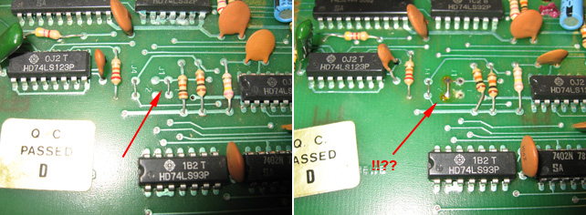
Figure 5. Jumper differences in the X-4020s! Working on the left, non-working on the right
I looked in the circuit diagram to see what J1 and J2 connected up to. There it was, J1 connected the FD pin with the input circuitry.

Figure 6. J1 jumper JOINING THE INPUT CIRCUIT TO THE FD DATA PIN!!
THE FD DATA PIN WITH THE INPUT CIRCUITRY!?? AAARRGGGGG!!!!
I moved and resoldered the jumper and plugged in the board and the cables. I switched on. The drive whirred! A stepper moved! The NEWDOS 80/2.0 banner was mockingly smiling at me from the screen.
I wanted to put my fist through it!
My emotions were part elation that a X-4020 was fixed, part-relief, and part-angst that such a simple thing had caused me such a huge amount of time and brain activity. I switched everything off and simply walked out of the computer shack.. I didn't return for three days!
Reflections
So this floppy controller issue was caused by moving a jumper. I have no idea what J2 was suppose to be for but it certainly disabled the drive, a hack applied for the school environment perhaps? It looks like these expansion boxes were only used to expand the 32k machines to 48k, and to act as supports for the screens.
Well, both are going 100% now. It's taken a while but I'm glad I persisted. More items from the System 80 haul now working!
Although this fix was frustrating, I take some solace in it. I was on the right track in feeling there was an issue with the input signal to the FD-1771, and solved the problem in the end. Also, I am learning more and more about how to read and follow circuit diagrams. I know way more about FD-1771 drive controller circuits than I used to, and maybe that's no bad thing. Lastly, I found using the digital camera to record and compare scope signals was a great technique! I'll use it in future fixes.
Tez
21st October, 2010
Postscript: After publishing this article I got talking to a few people regarding J1 and J2. Consensus is that this unit had a double density controller plugged in to the FD0-1771 socket at some stage. These DD cards have their own data separator so the jumper was moved from J1 to J2 to switch off the X-4020's own data separator. This is the input circuit I refer to above. When the board was removed the jumper was not reset. Either the person didn't know (or didn't care) that this needed to done.