Exidy Sorcerer BASIC ROM-PAC repair (Part 2) - ROM replacement with EPROM
Introduction
In the first part of this two-part project I'd diagnosed a problem with my Sorcerer BASIC ROM-PAC. The number 3 ROM had somehow zeroed all its contents! The next step was to replace this ROM with an EPROM containing the missing code. This was all new territory for me!
Blanking my existing EPROMS
In preparation for this I'd scrounged and purchased a number of 2716 and 27C16 EPROMS. However, all were used and contained code. I had to blank them. This was done with a newly purchased EPROM UV-eraser (Figure 1).
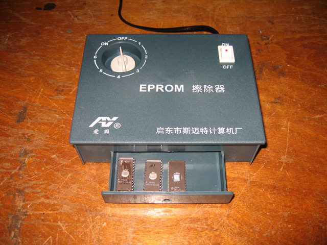
Figure 1. EPROM eraser from China. Cheap but effective
It was a cheap and cheerful device from China (obviously!) and didn't look too robust for industrial erasing. No worries. It certainly did the job for the few chips I wanted to blank.
Programming the 2716 EPROM
Prior to getting the eraser, I had two blank 27C16 chips which I had tried to program without success. For some reason the first byte was always bad? After the UV eraser arrived I could blank the 2716 EPROMS I had available. With this task done, it was time to fill one of these with 2k of correct binary code.
I inserted the chip, checked jumpers, checked dip switches, checked power, double-checked jumpers and started to insert code (Figure 2).

Figure 2. The Willem programmer at work on a 2716 EPROM
SUCCESS!! This time the code took! I now had an EPROM which could be substituted for ROM 3 of BASIC.
I still had some work to do though...
Rewiring the ROM-PAC
Even though the 2716 EPROM was physically the same as the masked ROM it was replacing it wasn't 100% pin compatible. Some re-wiring was required. Specifically pin 21 needed to be disconnected from ground and linked to 5 volts.
The ROM-PAC circuit board had handy solder pads and easy-to-cut jumpers specifically for this purpose. Using the circuit diagram, I found the pad corresponding to ROM 3, pin 21 and jumpered it to the 5V line. However disconnecting pin 21 from ground by cutting a trace also disconnected pin 20 from ground so I needed to jumper the pin 20 pad back to a ground pad (Figure 3).

Figure 3. Rewiring the ROM-PAC
After this was done the EPROM was inserted, and the repaired and reprogrammed ROM-PAC was ready for testing (Figure 4).

Figure 4. Rewired BASIC ROM-PAC with EPROM
Testing the ROM-PAC
After checking and double-checking everything, the time had come to see if my efforts had paid off. I inserted the naked circuit board into the Sorcerer (being careful to make sure it was oriented correctly), held my breath then switched on (Figures 5 and 6).

Figure 5. Naked pack inserted. Time for the big switch-on

Figure 6. Beautiful BASIC
WHOO HOO! There was the BASIC prompt, just as it should be! I typed a few lines of code just to satisfy myself everything was working properly. It was. Fix completed!
Reflections
As with many of my projects, I'm indebted to the guys from the classiccmp.org mailing list and the Vintage Computer Forums. Their guidance and advice, as always, was invaluable. In particular I would like to thank long-time Sorcerer owner and guru Pete Turnbull, who gave explicit guidelines on rewiring the ROM-PAC to take a 2716.
The project taught me a lot. Specifically this is the first time I'd delved into the world of EPROM programming. Before this project I always considered it a confusing and highly technical area that only hard-core hardware gurus could handle. Actually, it's not that difficult. Points to remember are:
- Don't rush things
- Be aware that voltages for programming and reading can differ between EPROMS. Use datasheets
- 27xx EPROMS may not be directly compatible with old mask ROMS of late 1970s/early 1980s computers. Some re-wiring or making an adapter is often required
I now feel confident to tackle other EPROM projects. I'm still puzzled as to why my Willem couldn't write 27C16s successfully? Thankfully I had 2716s so it didn't stop me fixing the ROM-PAC.

Figure 7. Exidy Sorcerer. Now with BASIC!
It's good to have my Exidy Sorcerer now fully working.
Tez
2nd July, 2011