Dead TRS-80 Model 1 monitor now lives
Introduction
Over the years I've slowly been building a full disk-based TRS-80 Model 1. A keyboard/console and expansion unit had each been separately sourced but I held out little hope of getting a badged monitor. Although any old composite monitor works with a Model 1 console, I wanted the real deal...a genuine Radio Shack TRS-80 Video Display monitor. After all they were an integral part of the TRS-80 Model 1.
As luck would have it one appeared on our local Trade Me auction site a couple of months ago. Whoo hoo! It was listed as faulty but none-the-less I was expecting to pay far more than the $1 reserve price. Imagine my surprised when there were no other bidders and the unit came to me for just that! Oh goody!!
Now I just had to fix it!
Initial inspection
The equipment was dusty and dirty when I picked it up but some elbow grease with a surface cleaner worked wonders. While it wasn't museum quality, it scrubbed up enough to be acceptable for a membership in my collection...assuming I could get it going!
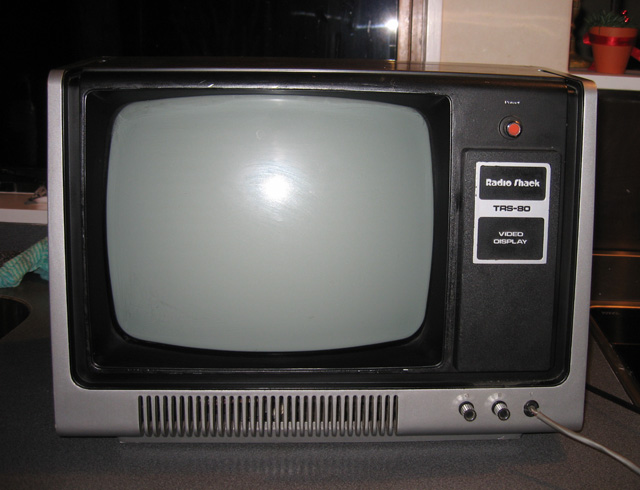
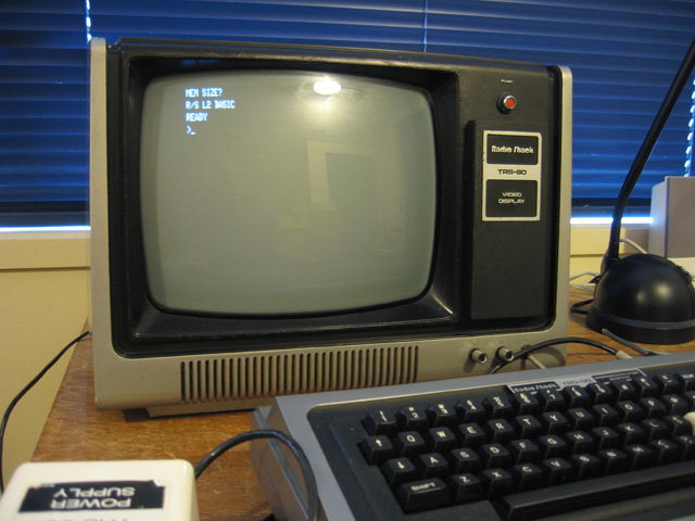
Figure 1. The Radio Shack TRS-80 Model 1 Video Monitor (now cleaned)
Switching on showed some signs of life, but not a lot. I could "smell" components heating up but there was no raster and no sign of the filaments in the neck of the tube. Time to get out the multimeter and the circuit diagram.
Diagnosis and repair
I sought help with this one from guys on the Vintage Computer Federation Forums (VCF) where a blow-by-blow account of the diagnosis and repair is documented. Rather than reproduce all the detail here, I'll summarise to a degree.
First a look inside the case of one of these 240V units.
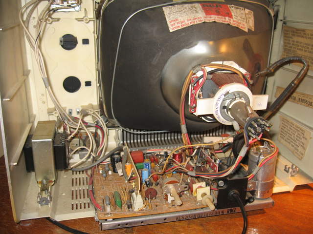
Figure 2. Inside this 240 TRS-80 Video Display Monitor
One interesting feature is the step-down transformer on the left, which converts 240v to 110V for use on the circuitry. This component also acted like an isolating transformer which meant this unit was not a "hot-chassis" model like some other variants. Whew, one less thing to worry about.
Whilst looking in the case I found one of the brackets holding the screen in place had broken off.
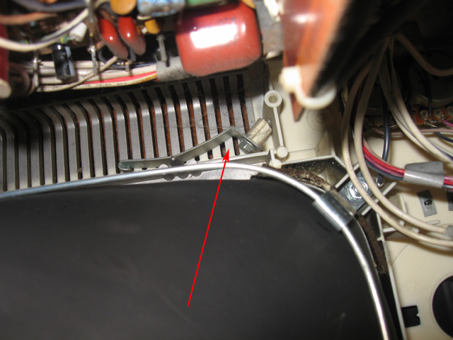
Figure 3. Loose tube securement bracket complete with snapped mounting at bottom of case
Luckily the bracket was still there lying at the bottom of the unit. Furthermore, there was enough of the plastic screw holder in the case left unbroken to secure this bracket back into place with a longer screw. The screen was now held nice and snug.
Guided by VCF guru Chuck(G), I worked through the circuitry, removing several layers of skin when testing some of the large "sand-block" resistors. Man, do those things get hot!. Do NOT use your finger to wipe away dust to check the markings if they've had current carousing through them!
There was also a Homer Simpson moment when I realised I was feeding the VCF guys AC voltages when I should have been reporting DC (Duh!).
Eventually we (well...ok...let's be honest...Chuck) determined the horizontal sweep signal seemed to be getting through to the Horizontal Output Transistor (HOT) but voltages were lower than they should be after that, leaving the HOT as a prime candidate as the cause. Another possibility was the Flyback Transformer itself. I prayed it wasn't the latter! Flyback transformers of this vintage are hard to source.
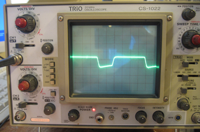
Figure 4. Horizontal sweep signal on the base of the Horizontal Output Transistor (a chance to play with my new 'scope!)
A check of the capacitors and diodes connected to the HO transistor showed these were ok. The transistor itself however was NOT as it should be. It had developed a partial short-circuit! Emitter to Base was showing 344 ohms in BOTH directions (it should only be one-way) and there was also 930 ohms showing between the Collector and the Emitter. These components do run under a heavy load and often give up the ghost. Could this be the fault?
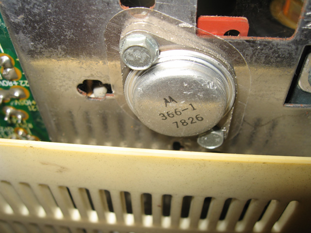
Figure 5. The faulty Horizontal Output Transistor in situ
A replacement transistor was sourced, fitted, the big red button pushed and the screen burst into life! Hooray!!
 .
.
Figure 6. TRS-80 Model 1 Monitor - It lives!
I left the screen going for about 25 minutes but no other faults were in evidence. Problem solved! The only remaining thing to do before reassembling was to solder on a new spark gap protector (a small NE2 neon lamp) on the tube neck to replace the one I'd accidentally snapped off (opps!). This was a trivial task though.
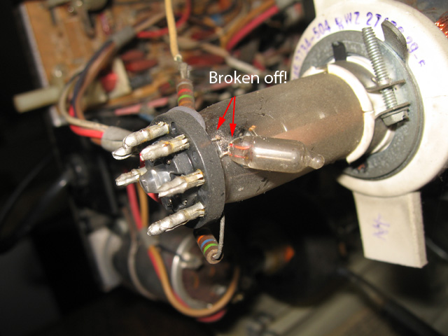
Figure 7. Snapped spark gap protector. Easily replaced.
Reflections
Chuck(G) from the Vintage Computer Forums helped guide me though this repair, and also helped source the replacement part. He has my gratitude. Thanks Chuck. Other folk such as MikeS, Modem7 and TRS-Ian (Ian Mavric) assisted too. A lot of my computers would still be dead if it wasn't for helpful guys like these.
Working on this problem taught me a lot about B/W composite monitors, which should prove useful if I ever need to do this again. I also learned that measuring AC on a multimeter is only ever useful for checking mains supply. If the AC is in a circuit, an oscilloscope should be used.
I'm now very close to owning a complete disk-based TRS-80 Model 1. All I need now are badged drive covers with internal PSUs and every part will be similar to what might have been purchased over the counter at Radio Shack in 1980.
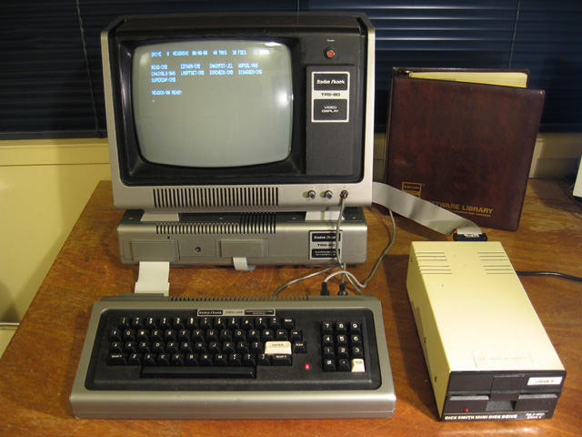
Figure 8. My TRS-80 Model 1 with Dick Smith System 80 Drive (yes, I know the colour clashes!)
Tezza
30th July, 2012