Checking out an Ohio Scientific Inc. Challenger 4P
Introduction
About six months ago I was left with a lot of Ohio Scientific Challenger gear. Amongst the detritus there were three naked Superboard IIs, a 5V PSU, a number of EPROMS/other chips, and a collection of boards, backplanes and paraphernalia in various states of hackery. Also this - A Challenger 4P. This article details my short adventure in getting it up and running.
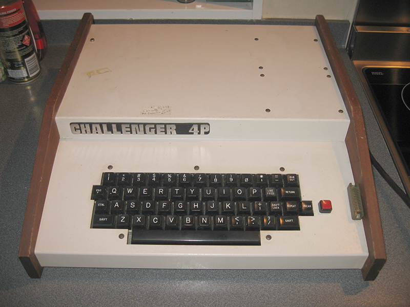
Figure 1. The Challenger 4P prior to cleaning and testing
First impressions
The computer looks iconic with its walnut sides and folded sheet metal cover. I love computers with this form factor. They just look so vintage! Check out the back. Enough ports and connectors to keep the most ardent hardware geek happy for hours! Impressive!

Figure 2. An impressive number of connectors!
Disk-based?
There was a floppy drive in matching livery amongst the gear. I assumed it came with this machine and that this was actually a C4P-MF model. The first thing I looked for was a floppy drive cable. Hmm...there wasn't one. Next I looked for somewhere I could plug a floppy drive cord into. There wasn't one of those either!
Undeterred I hooked up a monitor and switched on. What I saw was the classic frozen "garbage screen", meaning nothing was going to happen or was likely to. There was also the surprising sound of a fan.
The non-boot didn't faze me. I figured it probably expected a drive to be attached and was trying to load software. The Apple II and TRS-80 Model 1 freeze like this when a disk controller is present but no disk drive is attached.
A look inside
Even though I didn't have a disk cable I opened up the unit to see where it should attach. The computer opens in an interesting way. Essentially you flip it on its back, and remove the bottom.
Here is what I saw....
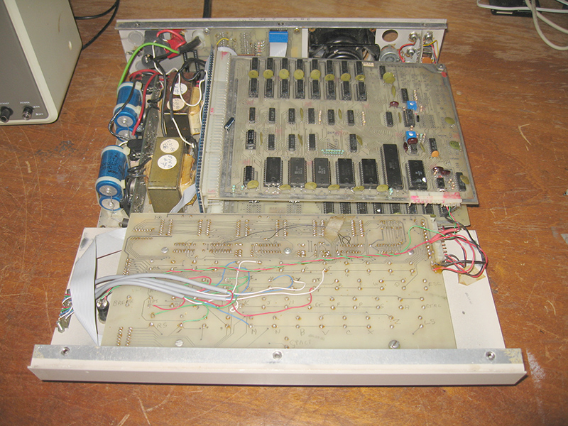
Figure 3. Challenger 4P revealed!
There were three circuit boards coming off a 4-board backplane, together with some daughter-boards in various places. On the other side of this were two identical PSU circuits. From the connection I could see that each PSU was dedicated to two boards each. I guess at the time it was cheaper or better to do this rather than to have one large PSU that had the grunt to feed all four. From photos I've seen, cassette-based units with only two boards were sold with just had one power suppy circuit fitted.

Figure 4. Three mainboards plugged into a 4-board backplane
Hmm...I couldn't find any connector which seemed to take a drive cable on any of the boards. Strange?? I decided to get some literature from the web just to figure out just what these boards were.
A cassette-based C4P, not a disk based C4P-MF
There are not a lot of OSI Challenger websites out there, but what ones do exist proved to be useful. Not only did I get a user's and service manual for the C4P, but I discovered this wasn't a disk unit after all. It was cassette-based. The main boards, from the top to bottom, were:
- A 502 CPU board (giving a cassette-based system with 8K RAM)
- A 527 RAM Expansion board giving an extra 24k of memory
- A 540 video board
I was disappointed it wasn't a disk-based machine but hey...it's still a C4P. But why did it have a disk drive associated with it? Your guess is as good as mine! The machine had the 527 board and the two identical power circuits which is more commonly associated with a disk system. I theorise this is a machine that was "downgraded" to a cassette unit, perhaps when the disk board failed? The disk drive was kept in case another disk board could be sourced.
So, I knew now what I was dealing with. The 527 RAM board was surplus to requirements at this point in time, so I removed it. I find when diagnosing problems it's best to start with the minimum configuration first. I would add the memory board later once I had the machine up and running. Scribbled in pencil on the board was "can be used with 502" so it seems it worked with this configuration.
Getting the machine to boot
The user manual told me pressing the <Break> key should clear the screen and give me the classic C/W/M ? boot prompt.
It didn't.
I thought I might have found the problem immediately as I noticed a track to pin 3 (the 01 (out) pin) of the CPU had been cut (who knows why?)!
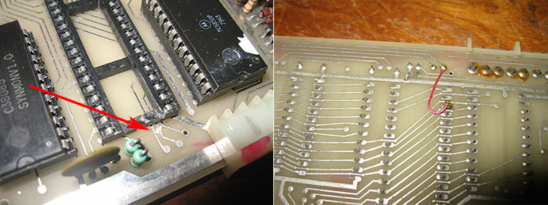
Figure 5. Repairing a cut track to the CPU
I jumpered the track, but the problem still remained. After working through the maintenance manual and trying the diagnostic tests there, I was still scratching my head. Everything seem to check out. I wondered if maybe the keyboard had failed?
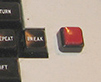 Luckily I accidentally stumbled on the solution. My machine has this big red button next to the Break key. Well I discovered that if you hit the Break key WHILE HOLDING THAT RED BUTTON DOWN then the machine indeed boots. Suddenly I saw the prompts!
I think that big red button was an after-market fitting, possibly added to stop the machine re-booting if the Break key was accidentally hit while typing.
After the friendly C/W/M ? was displayed I pressed C for cassette BASIC and yay! I was in!
RAM replacements
In...but not out of the woods. The bytes free showed 255 bytes! Where is my 8K? No problem though...I had come across this kind of thing before on my Challenger 1P. The SAMS manual showed me which RAM chips to suspect based on the reported number of bytes, and after two 2114 RAM substitutions the machine was showing its full compliment of 7423 RAM. Not a lot, but standard for a cassette model of late 1970's vintage.

Figure 6. Cassette-based Challenger 4P boot screen
I typed in and ran a few BASIC programs and the machine performed flawlessly. All the keys work. I really enjoyed the 64 column screen real-estate compared to the merge 22 columns my Challenger 1P can display.
Next minute...a keyboard issue!
I've played around with vintage machines long enough now to show that other problems can show up an hour or two after jolting machines out of hibernation. So it proved with this one. Just as I was concluding that everything was fine, something mysterious happened. On boot I could get to the C/W/M ? prompt, but after that nothing happened!??
Hmm...time to reach for the SAMs service manual again. It suggested RAM (no, wasn't that) or maybe ROM. I was hoping it wasn't the latter as I didn't see equivalent ROM chips in the spare parts pile. On a hunch (and out of desperation) I took the keyboard assembly apart and reseated all socketed chips. Hey, what do you know...that fixed the problem! Boot now went all the way again.
What about that extra memory board?
The 527 board seems to have an issue and I can't get the Challenger to recognise it. I'll write up that fix in a separate article if I manage to get it working.
Software
What software? I might need to write my own. Colour software for the Challenger 4P seems non-existent on the web. If you know of any, drop me a line. From what I've read the cassette-based 502 board in this unit has a similar (if not the same) memory map to the Challenge 1P, so C1P software might work. I've yet to try it.

Figure 7. A (seemingly) working Challenger 4P
Summary and reflections
So, I now have what seems to be a working 8K cassette based Challenger 4P (or Challenger II-4P as it should be more correctly written). It's a little disappointing it's not disk-based but I'm still stoked. Perhaps I'll source a disk board for it one day. For now, it looks great and I've decided to make it an official collection piece, to go alongside my Challenger 1P.
Of course I can't claim that it works perfectly 100%. For example I haven't tested out the colour capability yet, or any of the myriad of ports! That's for a rainy day when I've finished some other projects.
Tez
10th January, 2014