Adding composite video to a Sinclair ZX81
Introduction
Keeping alive the early "home" computers is a worthwhile thing. Not only can folk marvel at what could be done in 1 kilobyte of RAM(!!) but being able to touch and see history brings an understanding of how we got here today.
It's the "seeing" that's sometimes problematic. Some of those cheap early machines assumed the video output is the family television. However this was the family TV in the late 1970s/early 80s. The TVs of that era had only one signal input i.e. the antenna socket! Hence computer output was in the form of RF on a known channel, designed to be plugged into this aerial socket and the set tuned to the signal. The problem nowadays is that such TV sets are increasingly rare. Digital has replaced analogue broadcasting in many countries meaning TV sets are not designed primarily (if at all) for RF input. Even if they do have this capability, they may not be able to tune into the RF of an old home computer.
Such is the case with my current crop of TV/Monitors and my Sinclair ZX81. I USED TO have a monitor that could tune in (Figure 1) but that's no longer with me.

Figure 1. ZX81 with an old TV that used to tune into it well. I no longer have that TV though!
The existing TV/monitors I use for my home 80s computers all have RF input, but they don't tune in well to the ZX81 RF output. A picture would sometimes display, but it would be jagged and blurry. Composite video input is a much better option than RF and, as all of my TVs had composite input, I decided to explore modifying my ZX81 to this superior video output.
Getting information
I'd heard about this modification before and a quick Google revealed what was needed. Actually, the circuit appeared extremely simple! A transistor and resistor wired up to the appropriate inputs and outputs. Kits and made-up circuit boards could be purchased, but I felt I had the skills to tackle this mod, so tackle it I did. The job was made simpler in that I didn't want to ADD composite video capability; I wanted to REPLACE the RF video output with composite video. This meant no new socket was needed.
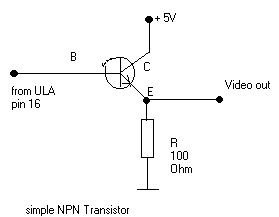
Figure 2. Circuit diagram for the composite video output
The circuit description didn't specify the exact type of NPN transistor. Since it said "simple" I figured a 2n3904 would do the job. I had some of these lying around in my parts bins.
Opening up the case
The first step was to open up the case. I'd never seen the inside of my ZX81 before so this was a first for me. A YouTube video was helpful in this regard, revealing that three of the screws are actually under the rubber feet, which I had to peel off for access. I figured I could glue them back on when I was done.
Figure 3. Screws hidden under the feet, in the back of the ZX81
Removing the case revealed the bottom of the circuit board (Figure 4). This also had a couple of screws which needed to come out before I could progress,
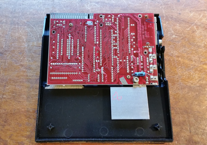
Figure 4. Cover removal revealed the underside of the mainboard
The board needed to be gently flipped over to reveal the components (Figure 5). I did this as carefully as I could. One thing I was acutely aware of was just how brittle and fragile the keyboard ribbon connectors would be...especially after 35 years!
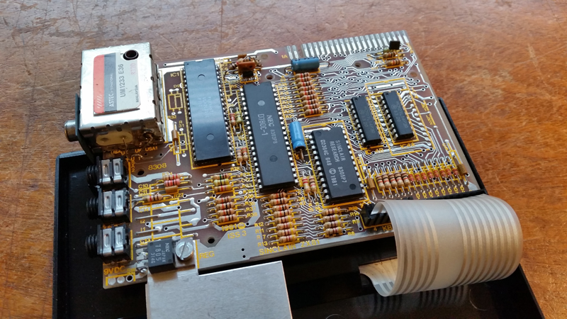
Figure 5. Top side of the ZX81 circuit board
Yes, that ole keyboard ribbon issue
Unfortunately, the trauma of movement was just too much. Inspection of the ribbons after inverting the board showed one of the two had partially torn close to the connector. Damn! However all was not lost. An article on the web suggested simply cutting the ribbon at the break, and seeing if the remaining section can be trimmed and re-fitted. Luckily the break HAD occurred right next to the corrector so there was plenty of ribbon left. I decided to do this after the mod. Figure 6 shows the right ribbon roughly cut at the tear, with the remainder of the ribbon still in the socket waiting to be extracted. The left ribbon was fine and has been completely removed from the socket (The ribbon is now standing vertically and is no longer bent, so edges at the top of the picture are the ones that would normally curl around and be inserted in the sockets).
The circuit board was therefore now free from the keyboard and could be worked on.
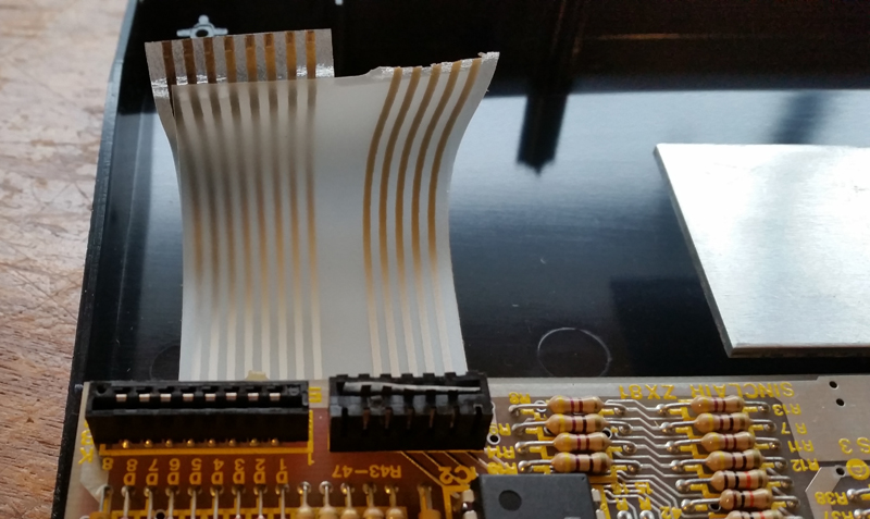
Figure 6. Keyboard ribbon removed. The right ribbon partially snapped near the connector. It's now been cut.
The modification
The RF box (Figure 7 lower left) had a cover on it which I removed. I could see there was enough room around the box for a couple of unmounted components providing I kept the leads short hence minimising the risk of the legs accidentally touching some other part of the circuit or the RF box itself.
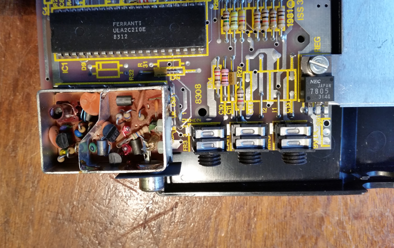
Figure 7. The RF modulator (lower left)
Figure 8 shows what's on the right hand side of the RF box when viewed from the back. There is a 5V line (right) and the video input from the ULA (middle). Also there is a spare hole going through to the RCA socket (left).
Figure 8. Right side of the RF box (Image from http://www.zx81.de/english/video_e.htm)
I decided the best approach was to snip that video line from the ULA and divert the signal originally destined for the RF box to the base of my transistor instead. I then wired up the collector to the 5V line and add the resistor to the emitter, the other end of which I earthed on the RF box. I then used a wire to grab the signal from the emitter (prior to the resistor) and threaded this through the spare hole. It was then a matter of unsoldering the RF output wire from the RCA socket and soldering on my composite video wire (coming through the spare hole). Figure 9 shows the finished result. Not pretty but it works!
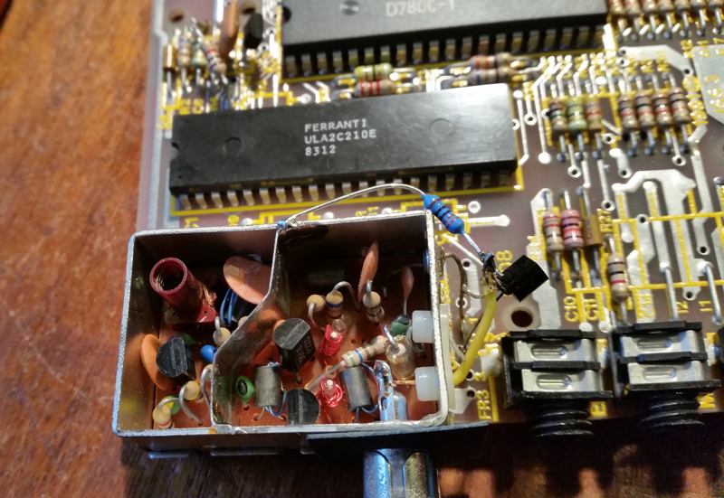
Figure 9. Composite video modification wired up
I made sure the desoldered RF line (which used to be attached to the socket) was well clear of anything else, as was the RF modulator end of the cut video input line. In fact I put a piece of insulation tape on them after the photo above was taken. I didn't want these now redundant lines touching anything else and causing a possible short or signal interference. However, I didn't want to remove them, as I wanted to option to restore the machine to its original configuration if needed.
I wired the mod up in such a way that I could replace the top of the RF unit when done. It just keeps things tidy (Figure 10)
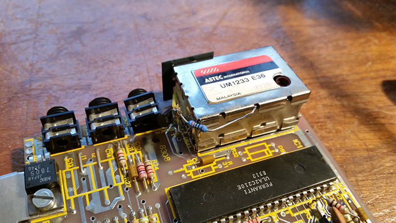
Figure 10. Lid replaced on the (now redundant) RF modulator
Testing
Now the mod was wired I needed to check if it worked. I had used a 220 ohm resistor rather than the 100 ohm recommended. This was simply because I didn't have a 100 ohm resistor at hand and the shops were closed. I'd seen a YouTube video where someone used a 200 ohm resistor without a problem, so I figured 220 was probably within tolerance. I needed to test it before fixing the keyboard issue though.
Plugging the board into the composite video input on the TV and applying power showed a nice clear K character (Figure 11). In fact it was the clearest I've ever seen a character from the ZX81. The mod had worked!
Figure 11. The ZX81 lives!
Fixing the keyboard ribbon
After extracting the torn ribbion from its socket with tweezers and squaring up and re-trimming the existing ribbon, the ribbon edges were ready to be plugged back into the connectors. This was easier said than done. Some force seemed to be required and I was concerned I would split the cable again. In the end I found the best way to insert these was to get one side of a ribbon seated first, then move along and press in the other pins. Eventually the two ribbons were soundly seated without damage (whew!)
Figure 12. Keyboard ribbon now secure
It was then just a matter of inverting the board, screwing on the back and re-gluing the feet.
The result
The end result was brilliant. Clear stable characters, the like I had never seen before (Figures 13 and 14)! A simple modification that works really well. I could now test and demonstrate this computer with ease.
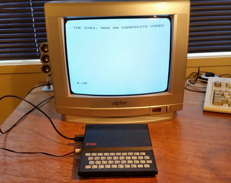
Figure 13. Beautiful clear characters from the ZX81

Figure 14. Testing the RAMPAC
Reflections
This is a simple mod, one that anyone with soldering experience can do. It's certainly worth it but I'd advise doing it in a way so that it's reversible. You never know when or if the original configuration is going to be desirable.
The main problem with this modification is it requires removing the keyboard ribbon so the board can be worked on. That's tricky, and I failed to do it without damage. Luckily, it was recoverable.
Tez
3rd January, 2016