NEC PC-8201a RS-232 Fault - Diagnosis and Fix (Part 1)
Introduction
The NEC PC-8201a (Figure 1) is a natty early portable out of the same Kyocera stable as the more famous TRS-80 Model 100/102. I owned a PC-8021a back in the day (1986 or so) and used it extensively at work and home, writing notes, drafting reports and recording data for experiments. All material could be uploaded easily to larger computers for final processing via the portable's built-in easy-to-use communications software.
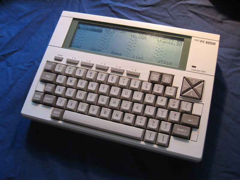
Figure 1. My NEC PC-8201a
Today, this computer is a well-loved item in my collection. Recently though, it had developed a problem. For some reason the RS-232 port had stopped working. It would neither transmit or receive anything!
A portable of this nature without an RS-232 for interfacing and file transfer severely limits its use. It needed fixing. Together with fellow enthusiast Philip Avery (Figure 2) a day was set aside to find the problem. Philip had recently acquired a PC-8201a himself and was happy to help.
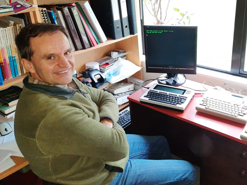
Figure 2. Philip Avery - Well-known in Model 100 circles for recently co-developing a CP/M implementation on this portable
Diagnostic Resources
For this task we used the following...
- A Windows 98SE machine running HyperTerminal through COM1. This allowed us to check transmit/receive of data.
- A null modem cable connecting the 98SE box with the NEC PC-through the RS-232
- An oscilloscope so we could trace signals through the components
- The NEC PC-8201a Service Manual w/Schematics, as downloaded from https://www.web8201.net
You can see the setup below prior to starting. Leaning the top of the PC8201a's case on the scope when opened meant we could check its screen and press keys if necessary (Figure 3).
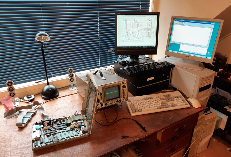
Figure 3. Workbench ready for the diagnostic session
Diagnosis
(i) Preparation
First Philip’s working PC-8201a was tested to see if it could communicate with the 98SE box over serial. Everything worked, which means the cable and 98SE box was ok. In contrast, my unit was completely dead to any RS-232 activity. Indeed, running a diagnostic program (found in section 5.2.4. of the manual) with loopback on wires 2 and 3 (Tx and Rx respectively) also reported a failure of the port.
Section 6.3.4 of the manual told us just what ICs to suspect. These were U30, U31, U21, U19 and/or U22.
With the PC-8201a in Terminal mode we opened the case in readiness to trace the any signals moving through the suspect ICs. We would generate these signals by keypresses on the SE98 box through HyperTerminal. Data would show up on the oscilloscope as pulsing changes in voltage (Figure 4).
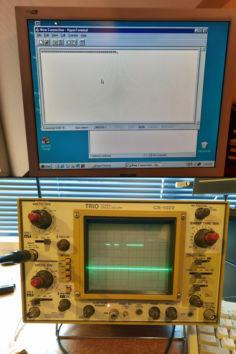
Figure 4. As letters were typed into HyperTerminal, data signals could be seen on the scope
Communication parameters were the same for each station of course.
It was possible to identify most of the ICs of interest on the motherboard, we had to guess U31 as its label could not be seen on the crowded circuitboard (Figure 5).
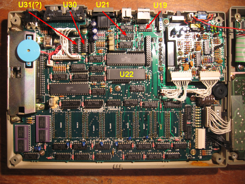
Figure 5. ICs of interest on the motherboard
(ii) Tracing the signal
Here we ran into our first problem. U21, U19 and U22 were identified on the circuit diagram in the manual. However, given the low quality of the scan we could only assume the logic gates shown coming straight off the RS-232 were U30 and U31. If there were identifiable U number on the gate symbols, they were too small to resolve. More than that though, when measured for connectivity, the pin allocations on the lines simply did not match up with the circuit diagrams? One possible reason is that the manual is labelled on the front page as being for model NEC PC8201 not NEC PC8201a. Perhaps the ICs for U30 and U31 differed between the two variants?
The good news is that the rest of the circuitry seemed to correspond to the circuit diagram and we eventually managed to trace the input signal arriving on pin 3 (Rx) of the connector to pin 10 of the U19 4DH153 multiplexor. This multiplexor is used to select data from RS-232, SIO1 or SIO2 serial input and sent it to the UART (U22).
(iii) Identifying the faulty components (we think?)
…And it was at pin 10 on U19 where the signal disappeared. There was no output (from pin 9) from U19 to the UART even though select lines (pins 14 & 2) were (correctly according the TC40H153 datasheet) set LO. Data should have passed. This pointed to a faulty TC40H153 IC at U19.
Replacement of a faulty chip is always the best option. However, SIO1 and SIO2 are never used (at least by me) so as a work-around we simply jumpered U19 pin 10 to 9 (on the board) while cutting pin 9 off the IC. We did the same with CTS signal (it wasn’t passing through U19 either) by connecting pins 6 & 7. In doing this we suddenly could receive data sent from the 98SE box. Hooray!
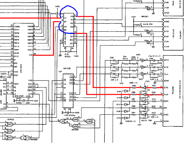
Figure 6a. Tracing and re-routing the Rx line
Hmm…we could receive data but we soon realized we couldn’t transmit it? Typing in Terminal mode on the PC-8201a keyboard showed nothing on HyperTerminal on the 98SE computer. We then found Tx wasn’t passing through U21 (TC40H139). Could this chip also be faulty? Assuming that was the case we bypassed the port selection process by jumping the Tx & RTS signals from input pins to output lines on the board whilst cutting off any possible output from the IC. This was similar to the work-around with U19.
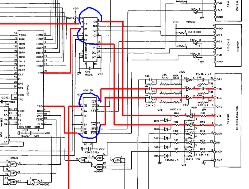
Figure 6b. Adding-in tracing and re-routing for the Tx line
Success! This final procedure got the RS-232 working fully. We could upload and download files and the RS-232 now passed its diagnostic BASIC program. The soldered jumpers can be seen in Figure 7. It's not a pretty piece of work but it does the job.
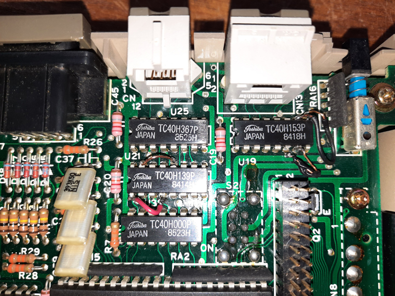
Figure 7. Jumper wires on U19 and U21
Reflections
The NEC PC-8201a’s RS-232 now worked. However we had come up with a workaround rather than a full fix. The problem had been solved by bypassing the multiplexor chips that source other serial I/O. What that meant was that SIO1 and SIO2, although they have no current use, could not now be used.
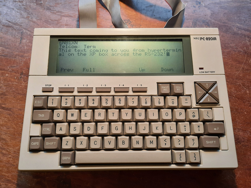
Figure 8. The NEC PC0201a is no longer incommunocado, in this case taking data from my XP machine.
We were still not entirely convinced that we have found the whole story, which is why we didn't yet want to simply purchase and replace both chips (assuming we could get them!). TWO ICs failing at the same time is a hell of a coincidence. If there is some other controlling circuity affecting both these ICS preventing data from passing through, then we had missed it.
In fact, we had missed something, as we discovered in a second diagnostic session. The rest of the story (and the final fix) can be read about in Part 2.
Terry Stewart
16th July, 2020
Edited 20th August, 2020