Pimped-out IBM PC (5150): Acquisition, Checkout and Repair
Introduction
I recently sold off superfluous bits and pieces of my collection which means I now have more room. What does one do with more room? Why, fill it of course, particularly if you are offered classic gear for free! So it was that I acquired this IBM 5150 (minus screen).
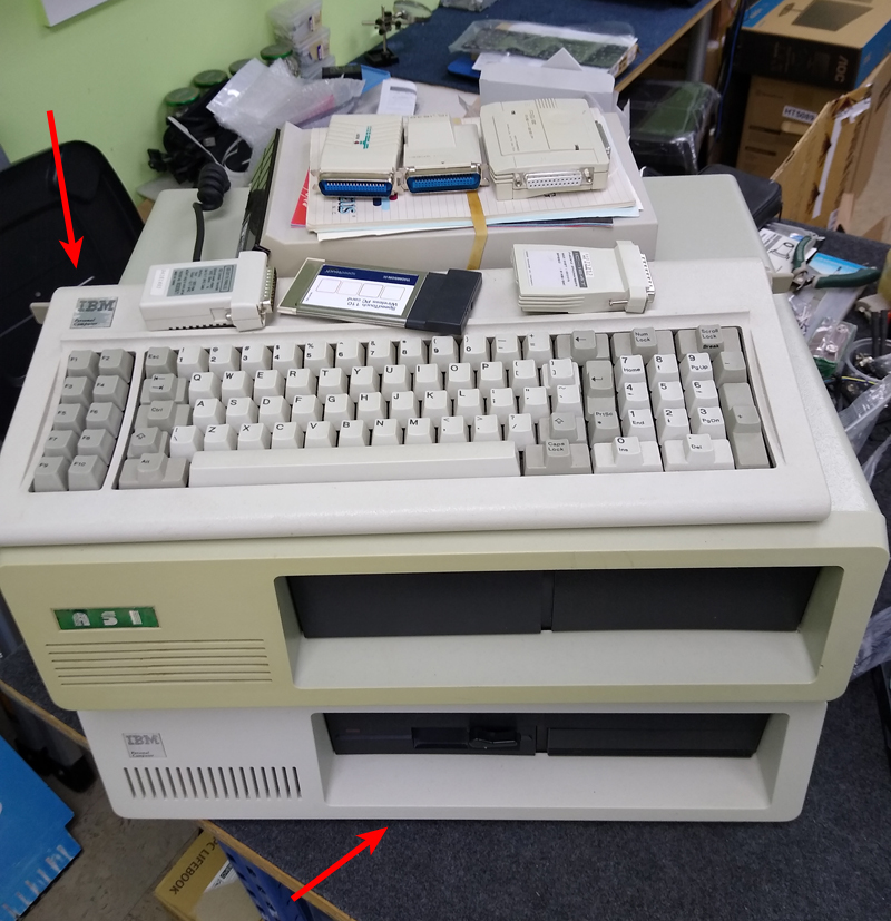
Figure 1. Freebies for pickup. I resisted temptation for the ASI and only took the IBM 5150
The machine was far from vanilla. A "standard" 5150 comes with dual floppy disk drives. In contrast, this one sported a ½ height 20 MB disk drive and a ½ height floppy drive plus these cards:
- Paradise Basic EGA card
- Six Pack Plus card which includes RAM expansion, calendar/clock and serial port.
- Another card with one serial and one parallel port.
- A Floppy and Hard drive interface card
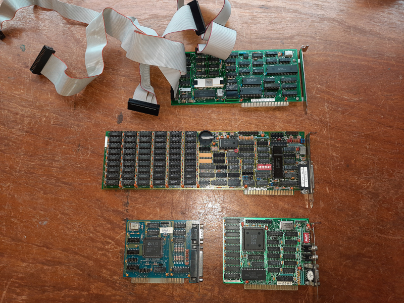
Figure 2. Cards which came with the computer
I knew there would probably be issues with this machine. After all, it hadn’t been powered-up for many years. With that in mind, I followed a sequenced power up/diagnostic process, leaning heavily on advice given in the excellent website minuszerodegress.net.
Testing the Motherboard and PSU
Once on the workbench I removed all cards, disconnected all drives plus the keyboard, made sure the dip switches on the motherboard reflected the current state of affairs and powered up. The PSU fan turned. I expected to hear a beep or a series of beeps. Nothing. I waited. Still nothing. Hmm.. Time to check the voltages from the PSU. Were they correct? Yes they were, which means the problem lay in the motherboard itself. I reseated all the socketed non-RAM chips on the motherboard to knock any possible oxidation off the IC legs and tried again. Still nothing.
(i) Checking RAM (Bank 1)
The problem could have been a number of components. However, one of the most common IC failures in these machines is RAM. The computer needs a certain amount of RAM even to “beep”. If bad RAM was preventing this, then the faulty IC (or ICs) was likely to be in the first bank of RAM.
Unfortunately, this bank was soldered into the board! Where chips are soldered in, it’s not a simple process just to swap them out. However, in some cases (not all) a defective RAM IC can be identified by piggybacking a known-good IC over the suspect one. If things then work, the suspect one is faulty (Figure 3).
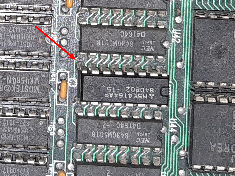
Figure 3. Piggybacked RAM
I tried this procedure, methodically piggybacking a good 4164 over the ICs hoping it would work..and it did work! When I got to the bit 5 RAM IC suddenly a long-short-short beep was heard. Progress! This IC was faulty. I extracted it and soldered a socket with a new 4164 in its place.
(ii) Checking other RAM
Now I had a beeps, I wanted to see what was going on. The EGA board had numerous dip switch settings so I decided to test that last. In its place, I plugged a working 8-bit VGA card into the board and connected a monitor. I also connected the keyboard.
Firing up the board I was pleased to see a cursor on the screen. Awesome! However, along with the beeps the numbers 2040 201 then PARITY ERROR 1 flashed up.
One thing nice about the IBM 5150 is that it checks memory on boot then tells you (via an error code) exactly what IC failed and in what RAM bank. Using the info in minuszerodegrees.net, I concluded this was the bit 6 chip in bank 2. I replaced it (it was socketed), rebooted and was then confronted with another message. Similar but different. In this case it said..3010 201 then PARITY ERROR 1.
What?? Another faulty RAM chip! This time the bit 4 chip in bank 2. This was the third RAM IC to be replaced (Figure 4)!.
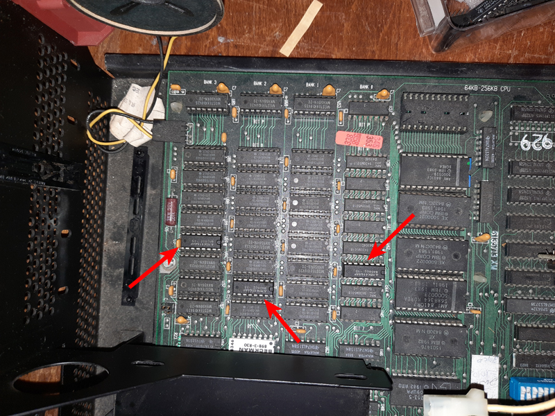
Figure 4. RAM replacements on the motherboard
The computer was rebooted again. This time there were no errors and the 5150 booted to ROM BASIC (Figure 5). Whew!
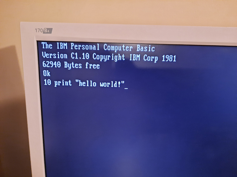
Figure 5. A successful boot to BASIC-in-ROM
Checking the RAM expansion card
Having ascertained the motherboard and PSU were OK (or fixed), I could now start adding cards. First up was the Six Pack Plus RAM expansion card. I dropped it in and fired up the machine. After somewhat of a wait, I eventually got the error code 6008 201 then PARITY ERROR 2.
Luckily, I had managed to find a Six Pack Plus manual online and this told me that a chip in bank 3 on the card was faulty (and which one)(Figure 6). It was replaced and the machine restarted. This time the computer booted up to ROM BASIC without error, although memory checking all 640k of RAM in these systems as part of the boot process makes for a long wait!
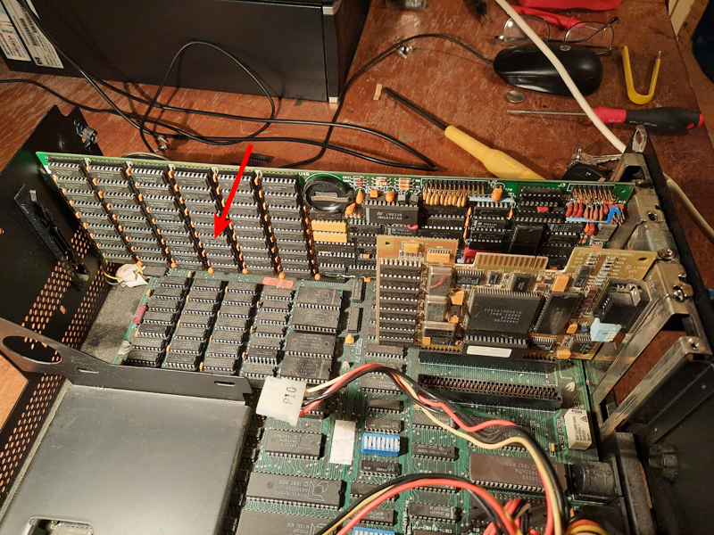
Figure 6. Position of the faulty RAM chip on the Six Pack Plus card
Adding the COM/Parallel card
I dropped this card in. The computer booted with no issues.
Adding the disk drives
It was time to add the disk drives back in. The drive controller card was installed, and drives plugged in (Figure 7). I was interested to see what was on the hard disk.
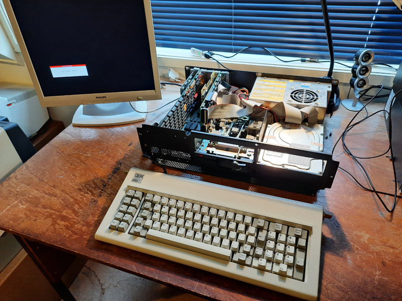
Figure 7. Drive testing about to begin
The big red switch was flipped and after a while, the computer loaded a TRS program or two then booted to DOS off the hard drive with no issues! Great!.
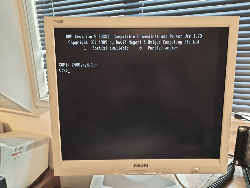
Figure 8. Booting to MS-DOS off the hard drive
However, there was a 601 error reported before the final screen appeared. This error indicated the floppy disk was malfunctioning. I had noticed that it did not activate like it should have.
I hoped it was something simple like a bad cable connection. I unplugged the cable from the controller card, reattached it, then rebooted. This time, the drive activated and there was no error. Hooray, it was that simple.
Would it read a disk though? I cleaned the heads, lubricated the drive rails then rebooted with a boot disk. Success (Figure 9).
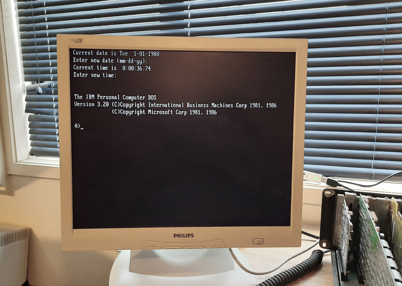
Figure 9. Floppy drive boot to PS-DOS 3.2
Checking with CHECKIT!
Now that all the cards (except the EGA card) were in and the hard disk seemed to work, I gave the whole system a thorough test with the testing utility Checkit! (Figure 10). All parts of the system including ports and drives all passed with flying colours. I was particularly pleased that the Mitsubishi MR-522 hard drive was sound.
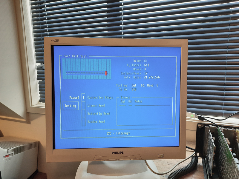
Figure 10. Checkit! doing its thing
Adding the Paradise Basic EGA card
There was one more hardware-related thing to do. Add in the EGA card. I wanted to link this unit up with a spare IBM Mono monitor I had lying around.
Information I found on the web suggested this card could put out a variety of signals and could be used with EGA, CGA or a Mono monitors, simply by selecting with dip switches and a jumper. Try as I might though, I couldn’t get it to work either with my CGA monitor or Mono one. I concluded it was broken until, in a last desperate act, I reseated the ROM chip in the card.
Suddenly it worked (Figure 10)! Some oxidation on the pins maybe!
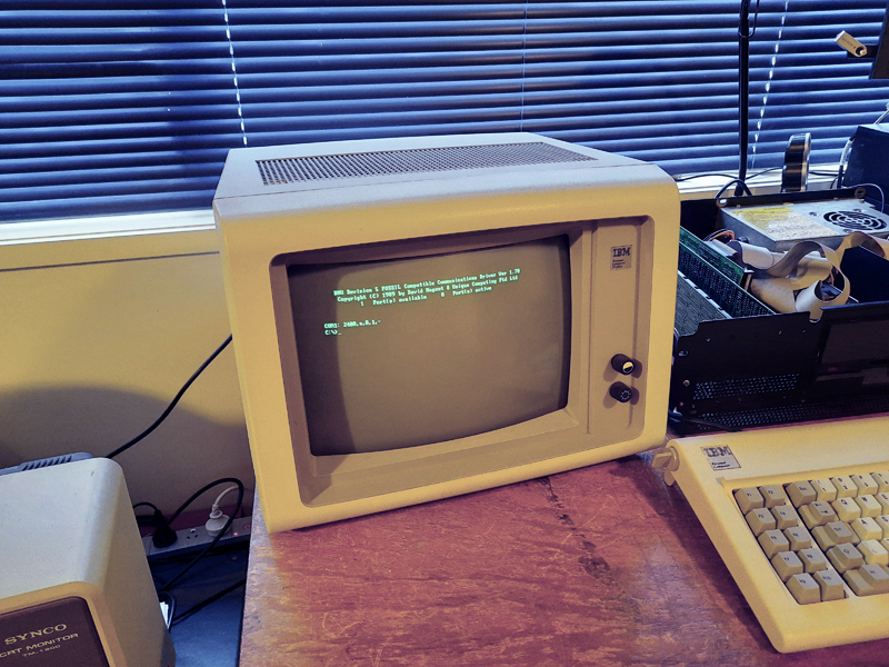
Figure 10. Video now working!
Figure 11 shows all cards now installed.
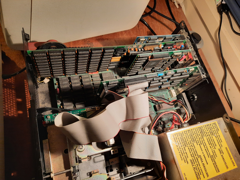
Figure 11. All original cards now re-fitted
Reformatting with PC-DOS 3.2
Strangely the hard drive had MS-DOS 3.3 installed not PC-DOS, which was normally associated with IBM computers of this era. As a last act, I reformatted the hard drive and installed PC-DOS 3.2 along with a game or two and some utility programs.
Now everything is as it should be (:
Final thoughts
Getting this up and running was fun. It was made easier by having lots of information about the machine and cards on the web. I was surprised a total of FOUR 4164 RAM chips were faulty! In my experience, where RAM has failed it’s seldom that many ICs. They really were bad chips rather than oxidation in the sockets, as reseating them didn’t make a different. Coincidence maybe, or perhaps this machine suffered some trauma in the past.
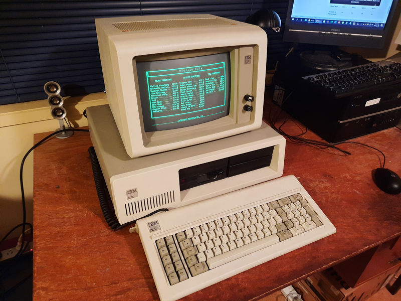
Figure 12. The pimped IBM PC, working and tested
Anyway, this pimped IBM PC is up and running and ready for action. As I write this it is 39 years since the IBM PC was released on an unsuspecting world.
Happy birthday Model 5150!
Terry Stewart
12th August, 2020