i have for sale some Boards for this awesome build if anyone wants them.. the price is for a pair of boards only no parts.. the cost for the 2 boards as a set is $20.00 + P&P (about $7.50 non rural)
message me if you want a set of boards (can also help with some parts as have some extras)
parts are still available from places like aliexpress, mouser, element14 RS etc..
Omega MSX Home Computer (open source)
Introduction
This project is an open source implementation of an MSX2 compatible computer. The project is built using a combination of 1980's era components -
Z80 CPU, V9958 VDP, AY-3-8910/YM2149F PSG, 8255 PPI, 7400-series logic, and some newer components, such as 512 KiB SRAM and 512 KiB Flash ROM
and a few simple programmable logic devices (ATF16V8B SPLDs).
New Zealand Vintage Computer Forums
Connecting New Zealand's vintage and classic computer enthusiasts
THIS FORUM IS NOW A READ-ONLY ARCHIVE. Similar discourse is now on Facebook. Click here!
Omega MSX 2/2+ Open souce
5 posts
• Page 1 of 1
Omega MSX 2/2+ Open souce
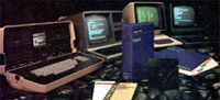
![]() by LS120 on Sun May 24, 2020 8:41 pm
by LS120 on Sun May 24, 2020 8:41 pm
- Attachments
-
- pic-1
- Omega-Keyboard_and_Mainboard-1.1.jpg (823.11 KiB) Viewed 14920 times
Last edited by LS120 on Sun May 24, 2020 8:51 pm, edited 1 time in total.
- LS120
- Posts: 499
- Joined: Fri Jul 22, 2016 9:19 pm
- Location: Wellington
Re: Omega MSX 2/2+ Open souce
![]() by LS120 on Sun May 24, 2020 8:41 pm
by LS120 on Sun May 24, 2020 8:41 pm
pic2
- Attachments
-
- pic2
- Omega-Mainboard-1.1-Back.jpg (248.98 KiB) Viewed 14919 times
- LS120
- Posts: 499
- Joined: Fri Jul 22, 2016 9:19 pm
- Location: Wellington
Re: Omega MSX 2/2+ Open souce
![]() by LS120 on Sun May 24, 2020 8:42 pm
by LS120 on Sun May 24, 2020 8:42 pm
pic-3
- Attachments
-
- pic-3
- Omega_Acrylic_Enclosure.jpg (214.58 KiB) Viewed 14919 times
- LS120
- Posts: 499
- Joined: Fri Jul 22, 2016 9:19 pm
- Location: Wellington
Re: Omega MSX 2/2+ Open souce
![]() by LS120 on Sun May 24, 2020 8:44 pm
by LS120 on Sun May 24, 2020 8:44 pm
there are also and open souce 3D printed case that when works well the stl will be given free to print..
- Attachments
-
- pic-4
- omega1-3.jpg (170.32 KiB) Viewed 14919 times
- LS120
- Posts: 499
- Joined: Fri Jul 22, 2016 9:19 pm
- Location: Wellington
Re: Omega MSX 2/2+ Open souce
![]() by LS120 on Sun May 24, 2020 8:50 pm
by LS120 on Sun May 24, 2020 8:50 pm
Parts List to build: (about $240nz) depends on where you get parts from..
Keyboard parts;
-----------------
U1 x 1 74LS145
U2 x 1 74LS07
D1 x 1 3 mm, green LED
D2 x 1 3 mm, yellow LED
D3 x 1 3 mm, red LED
Diode x 3 D4-6 1N4148
Keyboard Switch x 72 SW1-SW64, SW66-SW73 MX Cherry - Linear
Keyboard Switch x 1 SW65 MX Cherry - High Force Linear
Switch Leveling Kit SW13, SW49, SW64, SW65, SW73 Leveling kit for MX 1x2, 1x2.25, 1x2.75 5
Switch Leveling Kit SW64 Leveling kit for MX 1x8 1 to build a through hole leveling kit for the spacebar
Keycaps SW1-SW73 x 1kit 104 Keycaps kit for Cherry MX Keyboard
Connector x 1 J1 2x8 pin header, right angle, shrouded, 2.54 mm pitch
Capacitor x 2 C1, C2 0.1 uF, MLCC, 5 mm lead spacing
Capacitor x 1 C3 10 uF, MLCC, 5 mm lead spacing
Resistor Array x 1 RN1 4.7 kohm, bussed, 6 pin SIP
Resistor x 3 R1 - R3 470 ohm, through hole
Motherboard Parts;
------------------
U1 x 1 Z80 CPU, CMOS, 40 pin DIP - Z84C00xxPEG
U2 x 1 82C55 PPI, CMOS, 40 pin DIP - CP82C55AZ
U3 x 1 V9958 VDP, 64 pin DIP Note: V9938 VDP can be used instead
U4 x 1 YM2149 PSG, 40 pin DIP or AY-3-8910
U5 x 1 RP5C01 RTC, 18 pin DIP
U6 x 1 512 KiB Flash ROM, 32 pin DIP - SST39SF040
U7 x 1 512 KiB SRAM, 32 pin DIP - AS6C4008
U8 x 4 - U11 D41464, 64K x 4 DRAM, 18 pin DIP
U12-U14 x 3 Simple Programmable Logic Device - ATF16V8B
U15-U18 x 4 4-by-4 Register File - 74HC670, 16 pin DIP
U19-U21 x 3 74F541, 20 pin DIP
U22 x 1 74HCT540, 20 pin DIP
U23,U24 x 2 74HCT273, 20 pin DIP Note U24 is optional - printer port support.
U25,U26 x 2 74F245, 20 pin DIP
U27 x 1 74HCT175, 16 pin DIPE
U28,U29 x 2 74HCT157, 16 pin DIP
U30,U31 x 2 74HCT153, 16 pin DIPE
U32 x 1 74AHCT138, 16 pin DIPN
U33 x 1 74AHCT125, 14 pin DIP Note U33 is optional - printer port support.
U34-U36 x 3 Dual Flip Flop - 74HCT74, 14 pin DIP
U37-U39 x 3 74AHCT32, 14 pin DIP
U40,U41 x 2 74HCT30, 14 pin DIP
U42 x 1 74LS07, 14 pin DIP
U43 x 1 74HCT04, 14 pin DIP
U44 x 1 74AHCT02, 14 pin DIP
U45 x 1 74HCT00, 14 pin DIP
U46 x 1 Microprocessor Supervisory Circuit - ADM691A Possible alternatives: MAX691, LTC691, ADM691
U47 x 1 Sony CXA1645P RGB Encoder, 24 pin DIP-400
U48 x 1 MCP6281-E/P Operational Amplifier, 8 pin DIP
U49 x 1 LM311N, Voltage Comparator, 8 pin DIP Note U49 is optional - cassette recorder support.
Capacitor x 58 C1 - C58 0.1 uF, MLCC, 5 mm Pitch
Capacitor x 6 C59 - C64 220 uF, Electrolytic Note C62 - C64 optional - RGB output support
Capacitor x 3 C65 - C67 100 uF, 16V, Aluminum Organic Polymer
Capacitor x 3 C68 - C70 10 uF, MLCC, 5 mm Pitch Note C71 optional - cassette recorder support.
Capacitor x 7 C71 - C77 10 uF, Electrolyti Note C71 optional - cassette recorder support.
Capacitor x 1 C78 1 uF, Electrolytic Note C78 optional - cassette recorder support.
Capacitor x 2 C79, C80 22 nF, MLCC, 5 mm Pitch Note C79, C80 optional - cassette recorder support.
Capacitor x 1 C81 1.5 nF, MLCC, 5 mm Pitch
Capacitor x 3 C82 - C84 330 pF, MLCC, 5 mm Pitch
Capacitor x 1 C85 47 pF, MLCC, 5 mm Pitch
Capacitor x 2 C86, C87 33 pF, MLCC, 5 mm Pitch
Capacitor x 3 C88 - C90 30 pF, Trim Capactiors, 5 mm Pitch
Capacitor x 1 C91 27 pF, MLCC, 5 mm Pitch Note C91 should be 18 pF for PAL support.
Capacitor x 2 C92,C93 22 pF, MLCC, 5 mm Pitch
Capacitor x 1 C94 4.7 pF, MLCC, 5 mm Pitch
Resistor Array x 4 RR1 - RR4 10 kohm, bussed, 10 pin SIP
Resistor Array x 3 RR5 - RR7 4.7 kohm, bussed, 10 pin SIP
Resistor Array x 1 RR8 4.7 kohm, bussed, 6 pin SIP
Resistor Array x 1 RR9 470 ohm, bussed, 6 pin SIP
Resistor x 2 R2,R3 470 kohm, axial
Resistor x 1 R4 220 kohm, axial
Resistor x 2 R5,R6 100 kohm, axial
Resistor x 2 R7,R8 47 kohm, axial
Resistor x 2 R9,R10 20 kohm, 1% tolerance, axial Note R9 should be 16 kohm, 1% for PAL support.
Resistor x 4 R11-R14 10 kohm, axial Note R11, R12 are optional - cassette recorder support. Note R14 is optional - RGB output support.
Resistor x 1 R15 5.6 kohm, axial
Resistor x 7 R16-R22 4.7 kohm, axial Note R18 - R20 are optional - cassette recorder support.
Resistor x 2 R23,R24 2.7 kohm, axial Note R23, R24 are optional - cassette recorder support.
Resistor x 2 R25,R26 2.2 kohm, axial
Resistor x 7 R27-R33 1 kohm, axial Note R31, R32 are optional - cassette recorder support. Note R33 is optional - RGB output support.
Resistor x 1 R34 470 ohm, axial
Resistor x 1 R35 180 ohm, axial Note R35 is optional - RGB output support.
Resistor x 1 R36 120 ohm, axial Note R36 is optional - RGB output support.
Resistor x 6 R37-R42 100 ohm, axial Note R42 is optional - cassette recorder support.
Resistor x 6 R43-R48 75 ohm, axial Note R46 - R48 are optional - RGB output support.
Relay x 1 RY1 5V SPDT relay
Inductor x 1 L1 68 uH, axial
Inductor x 2 L2,L3 5.7 uH, axial
Diode x 1 D1 1N4148 Note D1 is optional - cassette recorder support.
Transistor x 2 Q1,Q2 PN2907A Note Q1 is optional - cassette recorder support.
Crystal x 1 Y1 21.477270 MHz
Crystal x 1 Y2 32768 Hz
Crystal x 1 Y3 4.433618 MHz Note Y3 is optional - PAL support.
Polyfuse x 1 F1 750 mA, radial, 5 mm pitch
Connector x 1 J1 DC Power Jack, 2mm
Connector x 1 J2 RCA Phono connector, Yellow
Connector x 1 J2 RCA Phono connector, White
Connector x 1 J4 Mini DIN 4-pos, Right Angle, PCB mount
Connector x 2 J5,J6 DIN 8-pos, Right Angle, PCB mount Note J5 is optional - RGB support; J6 is optional - cassette recorder support.
Connector x 2 J7,J8 Sub-D DE9M, Right Angle, PCB mount
Connector x 1 J9 Micro Ribbon 14-pos, Female, Right Angle, PCB mount Note J9 is optional - printer port support.
Connector x 1 J10 8 pin friction lock connector
Connector x 1 J11 2x8 pin header, shrouded
Connector x 1 J12 2x20 pin socket
Connector x 1 J13 2x2 pin header
Connector x 1 J14 1x13 pin header
Connector x 2 SLOT1,SLOT2 50 pin card edge connector
Jumper x 2 JP1,JP2 2 pin header
Jumper x 4 JP3-JP6 Wire link
Battery Holder x 1 BT1 CR2032 Battery holder
Battery x 1 BT1 CR2032 Battery
IC Socket x 3 U1,U2,U4 40 pin DIP
IC Socket x 1 U3 64 pin DIP
IC Socket x 2 U6,U7 32 pin DIP
IC Socket x 1 U47 24 pin DIP, 400 mil spacing Note: Cut the socket in the middle. If using a socket with 600 mil spacing, remove excess material. Alternatively, solder U47 (CXA1645P) without using a socket.
IC Socket x 11 U12-U14,U19-U26 20 pin DIP
IC Socket x 5 U5,U8-U11 18 pin DIP
IC Socket x 11 U15-U18,U27-U32,U46 16 pin DIP
IC Socket x 13 U33-U45 14 pin DIP
IC Socket x 2 U48,U49 8 pin DIP
- LS120
- Posts: 499
- Joined: Fri Jul 22, 2016 9:19 pm
- Location: Wellington
5 posts
• Page 1 of 1
Return to Vintage Items Available
Who is online
Users browsing this forum: No registered users and 46 guests