Ugh, I hate working on old boards with tiny pads that likely used lead-free solder which has aged and argh. In the future I'll be more careful, but it's so awkward, by the time you get the solder off you've lifted the pad.
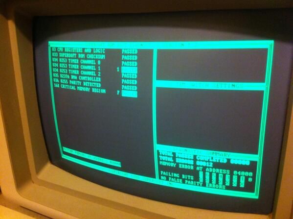
So anyway the new 74LS04 worked a treat, I've got a proper RAS signal on my RAM chips now and 9 times out of 10 I even pass my Base 16KB test! But I caused a wee bit of damage to the PCB (one tiny trace has gone + a bit of a mess) - and I'm not sure if the current memory errors are related to that (~50% chance) or it's something else again. With the circuit diagrams at hand, I should be able to repair the damaged trace correctly.
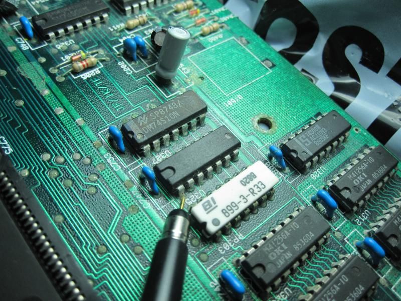
Here's a picture of the chip that failed - I've got the probe on the input (RAS0 I think), which gets inverted and pumped out to pin 2. It's also interesting that this failed chip is also the only chip on the board where the label is impossible to read (I needed the tech manual to know what the part number was):

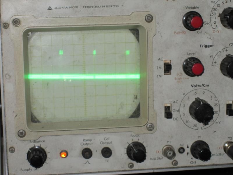
I forgot to take a picture of correct RAS, but this is what the inverse of RAS looks like (so picture it upside down I guess - +5V dropping to GND for a tiny bit).

(High five to my $1 oscilloscope)
RAS is used to select the row (CAS for column) but it's also used as a strobe to keep refreshing the memory. It's active low - so you should see +5V with tiny tips down, mine was just at +0V the entire time so the RAM didn't really have any chance at remembering anything.
So yeah, now I need to replace that trace I damaged, and see what happens and take it from there.


