Repairing a Commodore PET.
Now and again, you see old computers advertised on the auction site that are not working. Being a semi-literate as regards electronics I usually avoid these units like the plague. However, occasionally one comes up that is so rare, and externally in such good condition, you just can’t let it go. Such was the case with this non-working Commodore PET that came up for sale recently.
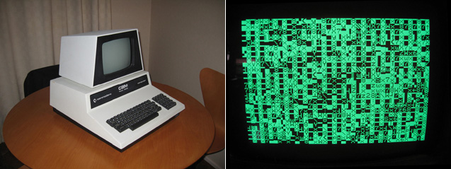
Photo 1 – One Recently-acquired Commodore PET showing the boot-up screen on right
When I purchased the computer I was confident I could fix it. After all, I’d managed to salvage some old APPLES recently, and in the process had learned much. Ah, ignorance is bliss. This confidence evaporated with three things quickly becoming apparent:
- Apart from the character generator, the ROMS and the CPU, almost nothing else was socketed. The “try it and see” approach I used with the APPLES was not going to be that easy here.
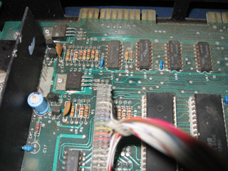
- While the external case and video were in excellent condition, the innards were not so luckily. While no mouse droppings were in evidence, plenty of corrosion and rust was. This CPU board was in a sorry state.
- There didn’t seem to be a lot of info. on just how these machines worked? I mean the detailed stuff, like the “Understanding your APPLE II” book for the APPLE II. Where was the PET equivalent
 Photo
2 - Rusty ICs on the circuitboard
Photo
2 - Rusty ICs on the circuitboard
Nevertheless, guys on the Vintage Computer Forum were supportive and helpful. I tried a few easy-to-do techniques like piggy-backing the RAM, to see if that made any difference. It didn’t. I also gave the board a good wash, cleaned and reseated all socketed ICs, and tried freshening up the solder around the sockets. No joy.
Eventually I decided the “diagnose and fix-it” challenge was just too big. I wasn’t even sure where to start, and I didn’t have the basic knowledge or tools (like an oscilloscope) to attack it from first principles.
Luckily for me, Anders Carlsson, a regular on the VC Forums, managed to source, and then send me a working equivalent CPU board! It had a different ROM from mine and the character generator had Swedish characters, but at least here was a chance the PET could live!
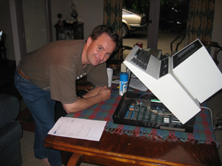
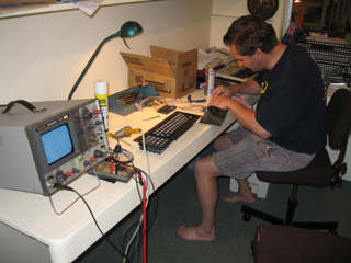
It still narked me that I had made such little progress on the original board. And (lucky for me) I wasn’t the only one interested in finding out what was wrong. Philip Avery, who had helped me with a Kaypro disk drive, had an interest in PETs. What’s more, Philip has some electronics training and an oscilloscope!!
As he did with the Kaypro drive, Philip offered to take the PET and see if he could find out what was wrong with it. And as I did with the Kaypro drive blog entry, I’ll let Philip continue this tale….
 Photo
3. Philip Avery scrutinising the PET
Photo
3. Philip Avery scrutinising the PET
Firstly I wanted to check the power supply with the scope. As well as the voltage levels, I was also looking & expecting to find ripple as this would explain why this PET wouldn't boot. This thing was nearly 30 years old, hadn't been used for a decade or two, so I figured a bad electrolytic capacitor in the power supply would be likely. I was wrong - no sign of ripple - power supply was fine. Hmmph. I then verified 5V was available at main ics. Then I focused on the 6502 CPU - checking signals going in & out were in order. Clock, NMI, RDY etc all ok. I established RESET was working correctly - going HI (non active) after half a second or so.
I then focused on the Address & Data buses. Here a mistake I made actually led me directly to a faulty ic. I was scoping the Data lines on one of the Video Rams (2114) when I noticed one was stuck HI. After exchanges with VC Forum personnel & increased study of the schematics - I realised this wasn't the CPU Data bus but the Video Data bus. Still, it shouldn't have been stuck HI, as all other data pins were swinging away, so I deemed that 2114 Ram to be dud. Replacing this made the Garbage Screen more random, but still no boot.
Further guidance from the VC Forum had me determining that the CPU Address & Data buses were fine. It appeared the CPU would operate for a short period from boot up (less than half a second), then hang. At this point the buses showed a different state each time, though a regular address was FFFFH. At this stage consensus felt the ROMs were a big unknown & a prime candidate - possibly providing the CPU with corrupt code causing the hanging. Internet searches revealed RAMs, Video RAMs and ROMs were the main causes of failure after Power Supply faults and ic socket/dry joints.
Fortunately Anders' board arrived & brought this session of faultfinding to a timely end.
- Philip
The new CPU board arrived from Sweden. The very next day, Philip and I had this inserted into the PET. A check of the jumpers showed they were set in the same position as the original board. In fact the only thing different about this board (apart from some socketed RAM) was one ROM chip less. The original board had five, this had four.
 Photo
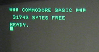
4. Successful Boot-up!
Photo
4. Successful Boot-up!
We flicked the switch and held our breaths. It booted up! Perfectly!!!. YES!!!
(nothing can compare to the thrill of seeing a dead computer come back to life before your eyes).
So…we now had a working PET. Well…kind of. On tapping the keys we discovered very few of them worked! Some did however, and some could be encouraged to do so. We figured it was a cleaning issue, which indeed it was (see later).
But what of the original board? Now we had a working item, we could swap the suspect ROMS into and test them. This we did and sure enough, the result was the same symptoms manifest by the old board after the 2114 fix. As Philip and some of the VC-Forum posters had suspected, one (or more) of the five ROM chips is faulty.
We then got brave and decided to put the new ROMS in the original board. If it was only the replaced 2114 and the old ROMS that were at fault, the board should work right? And indeed it did. Mostly. There were still a few odd characters on the screen in random places. It’s possible the other 2114 IC is also damaged. One day I’ll replace that and then we will know for sure.
 Photo
5. Screen bootup with good ROMS but faulty 2114
Photo
5. Screen bootup with good ROMS but faulty 2114
As a final check that the original 2114 was indeed faulty, Philip tried that component in the original board with the new ROMS. If the original IC was ok, we should have got a boot. Instead, we got the screen opposite. The IC was indeed bad. Good diagnosis Philip!
While doing this we discovered something about the ROMS. The ROMS in the original board were, in fact, BASIC 4.0 ROMS. These were not shipped with original 3032s so must have been inserted as upgrades at some stage. The board Anders sent us (the new board) had BASIC 2.0, hence had one less ROM. I was very pleased with this, as it made the new board authentic for the 3032 model, especially once we had swapped the Swedish character generator with the working English one from the original board.
 Photo
6. Philip on keyboard cleaning duties
Photo
6. Philip on keyboard cleaning duties
There was still the issue of the non-working keys? I did some googling and discovered this link that explained how to clean the keys and freshen the contacts. We didn’t go as far as complete disassembly as specified on the site but I did try the pencil trick on the pads whilst Philip cleaned the contacts with “Brasso”.
This worked, and soon we had the keys working. A few still require more than one press initially, but these might come right with a bit of use. I think it’s been a long time between drinks for this particular PET.
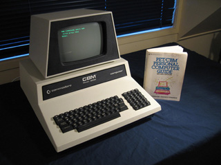 Photo 7. All fixed!
So, in summary, we now have a working 3032 PET, (albeit with the odd reluctant key) and a non-working spare CPU board, with a replaced 2114 video IC and bad ROM (somewhere). The second 2114 video IC may also be dodgy. The board now has a Swedish character generator (-:
Where to from now?
It would be good to find out EXACTY what ROM IC is faulty and to replace the second 2114 just to check if that was the reason for the extra characters on the boot screen. More projects for a rainy day.
This fix was a real team effort. These people deserve credit:
- Philip Avery for the hours of work leading to the correct diagnosis of the old CPU board.
- Anders Carlsson, for providing me with a replacement from the other side of the world.
- Finally all the guys on the VC-Forum for their encouragement and advice.
Thanks to all those above.
Tez
27th January, 2009
Postscript: The faulty ROMS have been identified. There was not one but two. One held memory address F000H-FFFFH (the Kernel) and the other held memory addresses B000H-BFFFH (start of BASIC 4.0) (5th Feb, 2009)
Postscript 2: The keyboard has now been replaced (14th November, 2009)