Adjusting the radial alignment a Tandon TM100 -2A drive without an alignment disk
Preface
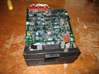 Many vintage computers of the late 1970s-early 80s came equipped with the Tandon TM100 -2A 5.25 inch floppy disk drive (seen opposite). These drives present a problem for vintage computer collectors. For whatever reason their radial alignment can change over time leading to a failure to read or write disks accurately. Screws exist on the drive for the adjustment BUT it requires a special alignment disk from Tandon which nowadays are rare as the proverbial hen's teeth!
Fellow vintage computer enthusiast Philip Avery describes a technique for radial adjustment of these drives WITHOUT the alignment disk. It still requires some gear, namely an oscilloscope, a computer capable of running a 5.25 inch drive and software which allows the computer to position the drive head over particular tracks. However it works, as can be testified by successful fixes for both my Kaypro and IBM PC Tandon TM100 drives.
Philip has documented this process and it appears below in his own words. The usual disclaimers apply . *WE MAKE NO GUARANTEES THIS WILL WORK FOR YOU. IN FACT, IT COULD RUIN YOUR DRIVE IF NOT DONE CAREFULLY. USE THIS METHOD AT YOUR OWN RISK*
Tez
28th June, 2010
Update: 6th November, 2010. Below Philip's method is another, simpler procedure described by Rick from Australia. Rick posted this on the New Zealand Vintage Forums in reponse to Philip's article. I haven't tried it myself, but appears useful to those without a scope or a TRS-80 Model III. I've copied and pasted the text into this blog posting. Read Philip's article first if you haven't already, alternatively jump straight to Rick's here.
Update 2: 4th September, 2022. If you try alignment by these methods but still can't seem to get a good signal or find the right track using software that parks you over one (like ImageDisk), it could be the stepper motor coupling. Check out this 2022 article which details our experience with a TPI (Texas Peripherals) drive. Tandon drives may have similar issues.
Introduction
The aim of this article is to show the steps required to radial alignment of a Tandon TM100 -2A 5¼” floppy disk drive without using the special Alignment Disk. This is intended for the Vintage Computer hobbyist who has some electronics’ knowledge, an oscilloscope and the desire to keep their 5¼” floppy disk drives operational.
Firstly, aligning a drive is not a “fix all” for lots of drive faults. Before any alignment adjustment is attempted, the drive must operate 100% reliably in its own right. That is - it must format, verify, read & write 100% reliably on a disk that has been formatted/written to only by that drive. If this isn’t the case, then those issues need tackling before the alignment is adjusted. All an alignment correction will do is enable floppies written by another drive, to work in this one, and vice versa.
The official & correct way is to use a special factory-produced Alignment Disk & adjust the drive so that an optimum signal is obtained. However these days those disks are becoming rare and expensive. An alternative (though not as accurate) method is to use a floppy that has been formatted in a drive that has known good alignment, ie a drive that can read/write to floppies generated by other drives. On a computer with two drives, it’s preferable to use a floppy formatted by that system’s good drive. We adjust the troublesome drive so that a peak signal is obtained while reading this particular floppy.
Procedure
1. Check that the “head split-band” screw on the stepper motor (see photo 1) is tight, as these commonly come loose, causing inconsistent tracking errors. Remove one plastic pin & swing cover to access this screw (photo 2).
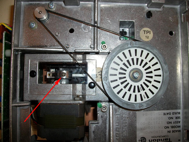
Photo 1. The head-split band screw on the stepper motor under its plastic cover
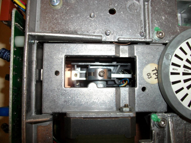
Photo 2. Plastic cover now removed allowing access
2. Bulk erase a floppy, then format it in a known good drive. It’s important to bulk erase it as this avoids aligning to old, possibly mal-aligned tracks and also verifies all 40 tracks are readable, ie the drive is not ‘one track out’. To bulk erase, I simply pass a strong magnet within about 20mm of the floppy & do several passes over the entire surface.
3. Insert the above disk in to the drive under test and direct the drive to seek a midway track, say track 20. I use a TRS-80 Model III to align these drives which has excellent Disk Diagnostic software (Floppy Doctor) which allows seeking to any given track. Once there, it will continuously read a given sector & ignore any errors. If you can’t find such software for your system, usually it’s possible to construct a small program in Basic to achieve this.
4. Connect scope to TP1 or TP2 (ground of scope to TP6) & you should see a signal of 0.3V to 0.6V peak to peak (see photo 3). On my scope I use these settings: 0.1 Volts/div and 20 usecs Time/div. (If you can’t see a signal, replace the floppy in the drive with one that has been written successfully to by that bad drive. This will show the best-case signal – what you’ll aim for when reading a floppy from a good drive. This will also verify your scope settings, connections. Once a signal is established, re-insert the above floppy from a good drive).
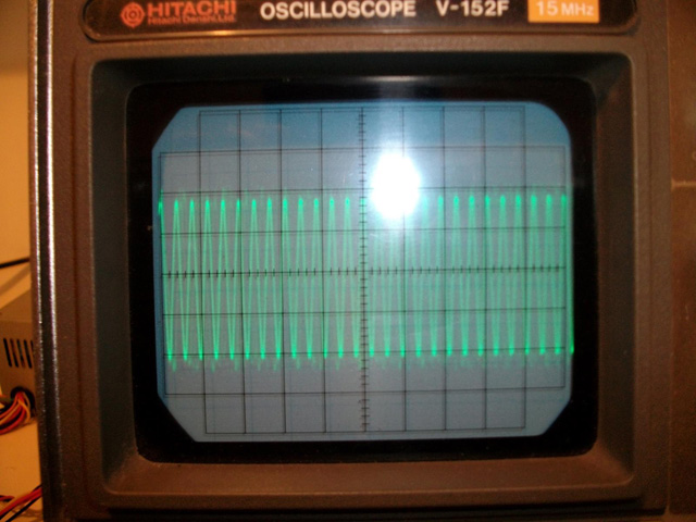
Photo 3. A strong signal from the drive head positioned over a track
5. Loosen the two retaining screws underneath (see photo 4) and the one on top beside the Adjustment cam (see photo 5). To avoid shorting the pins above the Adjustment cam, either protect these with some insulation, or use an insulated-shank screwdriver to adjust the cam screw. (see photo 6). Turn the cam slowly, no more than half a turn in any direction, while observing the scope and aim for the maximum signal.
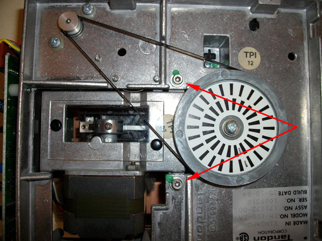
Photo 4. Retaining screws underneath drive
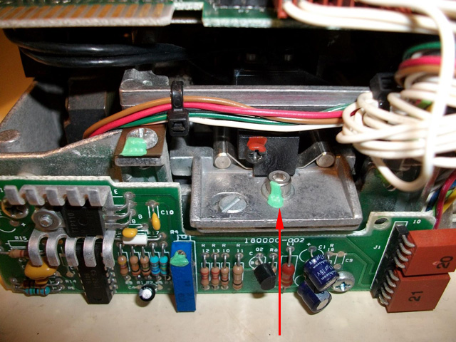
Photo 5. Top retaining screw
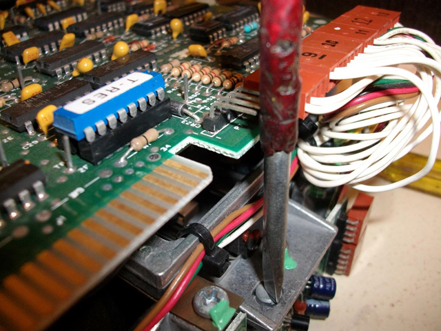
Photo 6. Adjusting the cam screw. Note the insulation to prevent shorting of the pins on the circuit board
6. At this point I lock the top retaining screw (only mildly tight) then step over the disk to ensure all tracks produce a decent signal. It’s worth noting that with the higher tracks (above say track 30), it is normal that there is a substantial drop-off in signal as there is less media in those inner tracks (smaller circumference). This is why the signal strength ranges from 0.6V down to near 0.3V for a good drive. Sometimes it takes several adjustment attempts to get an overall good signal. I then lock down all three retaining screws.
7. The next step is to verify the drive is aligned to the given correct track. It is possible to adjust the cam to read an adjacent track, so for example you could be set-up to read track 1 to 40, not track 0-39. Using Floppy Doctor’s stepping function, I start at track 40 (one beyond the proper track count of 0-39) and ensure that there is no signal (hence the need to initially bulk erase). I then step back to 39 which is where the first sign of signal should occur. Then continue stepping & eventually reaching track 0, ensuring there is a good signal there and that the track 0 sensor activates. It shouldn’t be possible to step further back than Track 0.
Your Tandon drive should now be able to interchange floppies with other floppy disk drives.
Philip Avery
23-Jun-2010
The blog post was very timely for me (thanks Tezz and Philip). I have a pair of these Tandon TM100-2 5.25" floppies in my S-100 machine and one had drifted off alignment over a long period.
I started following it through, and have now got my second drive nicely aligned, but with some deviations. Let me suggest a couple of extra points.
First - use ImageDisk for the control and testing - it's free and very versatile. I don't have a TRS-80 so thought I might have to write some code to goose that read signal for the scope. Then I had another look at the Alignment module that is part of Dave Dunfield's excellent ImageDisk free utility (DOS platform - reads, makes images and writes to any floppy format incl CP/M). Easy to Google it.
Hooking the Tandon up to a PC, I used the ImageDisk align utility to quickly find out that my problem was not just alignment, but one of the heads not firing at all. I took the controller board off the drive, and noticed that the diskette had a buckle in it where it passed between the heads. The plastic frame that sits on top of the aluminium chassis may have shrunk a bit over 30 years, or I may have pressed it back into position too firmly after cleaning out the drive, or maybe a combination of both. Anyway, with these drives it is worth checking that the disk slot is exactly at the right level for the fixed head. Problem fixed by levering one or two of the plastic holding posts about 1mm out of its snug hole in the aluminium chassis. The test for correct position is easy - the disk slides in without pushing, shoving or twisting!
I had hooked up my scope as instructed, but it turned out that ImageDisk provides an easier check on your console screen. You can navigate the heads to any cylinder/track and read one head at a time for data. It just keeps reading the same track till you tell it to do something else. Once I had adjusted backwards and forwards till I could read data consistently on both heads at track 20, I just stepped through all the tracks, both sides, and made finer adjustments to ensure they were all reading correctly.
Then ImageDisk can do test reads and writes for any track. I'd recommend confirming outermost, innermost and centre tracks at least, before you are satisfied and start tightening up the screws again. Keep the drive in the test rig and keep testing while you gently tighten the screws one at a time - the tightening can be enough to nudge it a fraction off alignment.
The scope test will give a more fundamental hardware spec alignment, but read and write were enough for me!
I also recommend going the extra step of taking the controller board off the drive for the adjustment process. It is only held by two screws then a slide and a wiggle. Unplug all the cables first.
Carefully unlace the two sets of head cables, that come from the front of the drive, from their cradles in the plastic frame. You can then re-connect the board standing on its end at the back of the drive, loose from the chassis. Then run your tests and do your adjustments with all the mechanics of the drive in full view, and with most electronics out of the way of screwdrivers, crowbars, chainsaws or other tools you may be using. Just be careful that there is some slack in the head cables while the board is in that position, so the cables do not put any drag on the head carriage and inhibit its movement.
I found it much easier to control the fine adjustment of that pretty crude cam screw with the board out of the way.
Rick
s100fan(at)gmail.com