Restoring a System 80 / Video Genie/ PMC-80 Part 5: Adding a switch for sound
 Introduction
This is the fifth (and possibly final) part of a restoration project which started when I just couldn't leave a non-working System 80 alone. So far...
- defective RAM has been repaired (or rather a defective 48k mod was removed to obtain a working 16k)
- a video fault has been fixed
- the cassette recorder has been repaired once and repaired again!
- a switch has been added to reverse the external and internal cassette drives
- a damaged case has been replaced with an acceptable one
There was one more modification crying out to be done before I finally put this machine to rest. The replacement case sports two small holes at the back for microswitches. It was easy to guess what these might have been for. One would have been for switching cassette control from the internal deck to an external one. The other would have been to enable sound to be driven to the external cassette OUT line, so TRS-80 Model 1 software would act just as it does in the Model 1.
These were two common System 80 black-label modifications. I'd already added the cassette switch. Now it was time to add the sound one too!
The modification
The modification is documented on my System 80 website (figure 1). It is a fairly simple process. The hardest thing was deciding exactly where to solder in the lines.
Figure 1. Schematic for the sound modification
I found there wasn't much room amongst the components even for a small soldering iron. In fact it was so cramped I grazed a capacitor in the process (Figure 2) - oops!
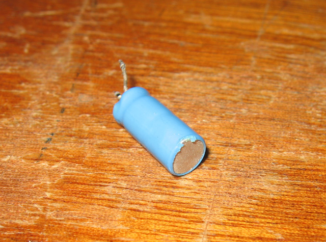
Figure 2. A capacitor which has felt the gentle touch of a hot soldering iron!
The damage seemed minor but I replaced the capacitor anyway. I figure the parts are cheap enough. You can never go wrong replacing caps.
Eventually I managed to solder in all the switch leads (Figure 3). Not wanting to abuse the board any more than necessary I decided not to cut the track between the anode of D10 and the 9V line. Instead I just pulled the D10 anode lead out of the board itself and soldered it to the switch. If the modification was ever removed, it's tidier simply to re-insert that end of the component rather than bridge a cut track.
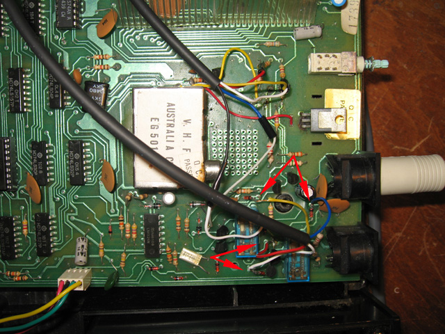
Figure 3. Arrows show the connection points for the sound switch
Once I was finished on the video board, I wired the switch end up and tested the modification. I plugged the cassette #2 OUT line into some PC speakers and loaded in Meteor Mission off cassette. Would it work?
The result
Perfect! The beeps and blips were loud and clear, just as in my other units and my TRS-80 Model 1.
To finish off it was then simply a matter of carefully inserting the switches in the back of the case and screwing everything back together (Figure 4).

Figure 4. The cassette (left) and sound (right) switch mounted at the back of the case
Reflections
When I first started this project, I was looking to restore a sad micro to the original state. That concept was soon discarded once I decided the case HAD to be replaced and the only other case I had was a modified one. Having extra keys and two holes begged for cassette and sound switches, I just had to add them. This computer now has many of the "improvements" System 80 hardware hackers added to their black-label units back in the day.
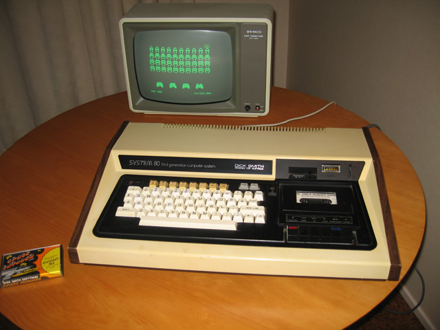
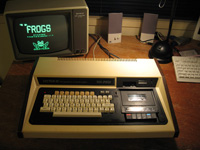
Figure 5. The restored and improved Dick Smith System 80
Although the replacement case is not pristine, this latest member of the collection scrubs up pretty well (Figure 5). However, if I really WAS a hardware hacker back in the day I wouldn't stop here. I'd (re-)boost memory to 48k and probably add a joystick port too (the case already has a DB 25 for this). However, I'm down on 4116 ICs though and although I could use 4164s for a memory expansion this requires cutting tracks. I don't like permanently altering classic gear unless I really need to.
Perhaps one day I'll add some more modifications. Or maybe I'll try the market again. Someone might be interested, now that further fixes and improvements have taken place.
Tez
30th July, 2010