Repairing two faulty Commodore PET mainboards - Part 1
Introduction
 Commodore PETs are great old classic machines. Old can mean cantankerous though. They don't like to be handled and are known to simply stop working, especially if you poke around inside. Such was the case last week. In fact not only did my PET fall over in a screaming heap but a spare mainboard which had nearly been fixed previously also regressed to a comatose state!
What caused this state of affairs and how was it fixed? Read on..
From almost two working mainboards to zero
Having just finished upgrading the ROMS in my working PET I was "in the zone" as far as these machines went. That being the case I decided to tackle a problem that had been on the back burner for about 18 months. My PET's original faulty motherboard had been replaced. I'd kept this original board with a view of trying to repair it sometime. Now I had a spare set of working ROMs to install in it, I decided that day had come.
As far as I knew this board had a faulty video RAM 2114 chip. Not seriously faulty, just enough to put a few spurious characters on the screen. It should still boot up. To see it live again I repopulated the old board with the (now spare) BASIC 2 ROMS and switched on. I expected to see the familiar Commodore BASIC screen with the odd funny character lying around caused by the bad video RAM. Instead (and to my dismay) I was greeting with a "garbage screen", a very generic symptom which told me my PET board had something more significant wrong with it.

Figure 1. The old familiar garbage screen (from another PET episode)
Oh boy...
Hmm...maybe the CPU or one of the larger chips decided to fail. To check I swapped out the CPU. No improvement. I tried the BASIC 4 ROMs in place of the BASIC 2 ones. Hmm..this time I got to the BASIC startup message but no cursor or keyboard response? OK, something was seriously wrong.
However, worse was to come. I replace the chips I'd swapped out of my working board...only to find that board now wasn't working either!! A few funny characters were displayed on a frozen screen. What??? Oh gawd.. Now I had TWO broken PET boards!
The problem with the spare board
I decided to tackle these problems one at a time starting with the spare (i.e. original to this PET case) board.
As usual I got a lot of help and encouragement from the guys on the Vintage Computer Forums. One of the inhabitants (Eudimorphodon) had written a PET TESTER. This small piece of code, run from an EPROM placed in the F000 (Kernal) ROM socket, tested some basic CPU functions and the first 1KB or so of RAM. Using my new-found EPROM programmer skills I put this code into a 2732 EPROM and wired up an adaptor (thanks dave_m) so it was compatible with the 2532 sockets found in the PET.
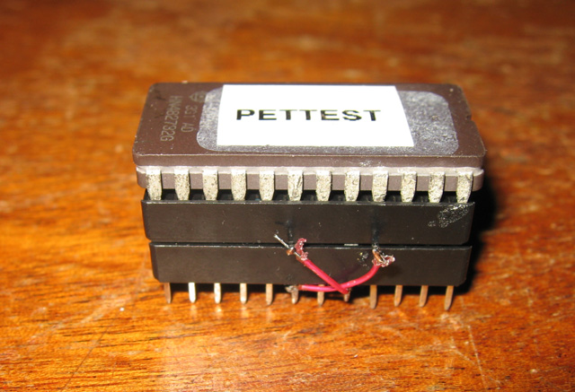
Figure 2. The PET Tester ROM and adaptor
After checking a number of things and swapping chips around, I had noted the following:
- The PET TESTER showed no CPU activity
- The BASIC 2 ROMS showed a garbage screen
- The BASIC 4 ROMS kinda worked. At least they got to a splash screen but there was no sign of a cursor or keyboard response.
This was weird? If BASIC 4 worked then the CPU was working so why did the PET TESTER fail? Also, why was BASIC 2 not working when BASIC 4 at least got to the splash screen? All ROMS were checked in the EPROM programmer and they were good!
Diagnosis
Philip Avery helped me with this. He bought his scope over and we sat down at the workbench Saturday morning and went through a number of diagnostic tests together.
One of the first tests was a simple one to see if there was connectivity from all ROM sockets (Figure 3).
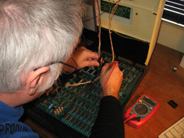
Figure 3. That's me checking for socket connectivity
This test revealed the first fault. A damaged E000 ROM socket which wasn't allowing pin 8 of the BASIC 2 masked ROM to connect. However, the BASIC 4 E000 chip was an EPROM with longer legs and this did connect. This explained why BASIC 4 got further along the boot process than BASIC 2.
With this problem identified, the next issue was the lack of cursor or keyboard. This symptom pointed towards the PIA chips, specifically the one at C7. We checked this chip for power. What? 0 volts? It seems this socket too was faulty and the 5V number 20 pin wasn't receiving any juice. I soldered this up to a 5V source on another part of the board (Figure 4) and (at least with BASIC 4) yes!! A working machine (albeit with some spurious characters from the faulty 2114)!
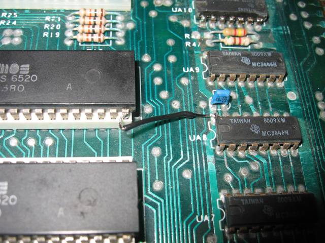
Figure 4. Supplying power to the PIA via a jumper
So, the problem was two faulty sockets. Philip didn't even have to use his scope!
But why hadn't the PET TESTER worked? We discovered the answer to that too. Short legs! The adaptor was made of two sockets with a couple of pins crossed over. On the bottom socket the wires were soldered to the top of the pins but even so, it made the pin length that could go in the socket just that much shorter. Too short in fact. What confused us that in the OTHER PET board this device worked, even with short pins (more on that in part 2)! Just the differences between sockets on the two boards I guess?!
The Fix
Here is what I did:
- Replaced and socketed the second 2114 Video RAM chip (Philip had already replaced one)
- Replaced the E000 socket
- Jumpered Pin 20 of the PIA (6520) in the faulty socket to a 5V power source on the board
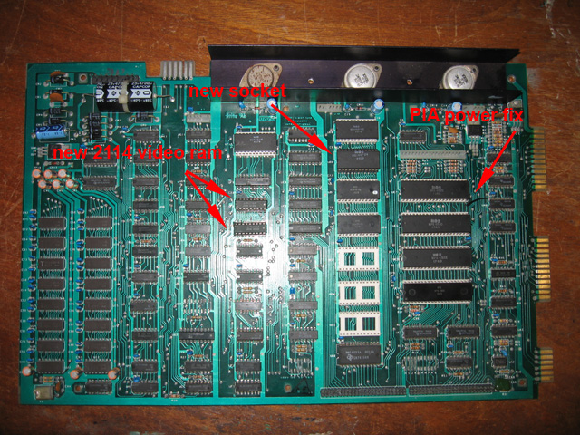
Figure 5. All fixes required to make the board workable
Why didn't I replace the 40 pin PIA socket? I found replacing the sockets quite difficult. In fact I accidentally lifted a couple of traces while replacing the ROM one. I managed to successfully jumper the pins in question under the board so the lost connectivity was restored but the experience made me wary of desoldering something even bigger. I decided a short neat jumper soldered onto pin 20 and connecting to a nearby 5 volt pad on the board would be fine.
The next step
I had a working PET again. Phew!
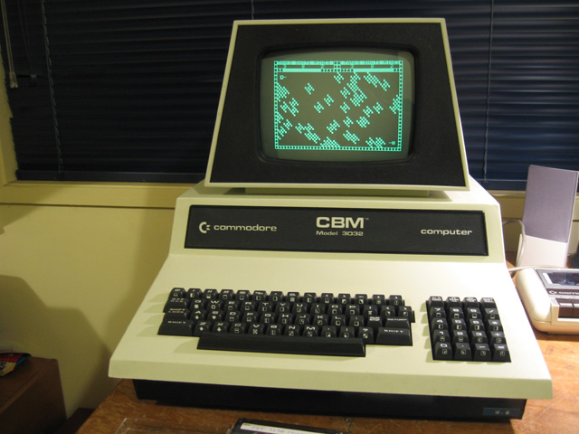
Figure 6. The PET playing Tanks!
My work wasn't finished though. I'd started with a working PET and non-working spare board. Now the spare board was working but the once-working original one was not! The diagnosis and repair of this problem is covered in part 2 along with some general reflections on repairing Commodore PETS.
Tez
14th July, 2011