Aligning a full-height floppy disk drive when the alignment screw proves inadequate. Check the stepper motor coupling!
Introduction
Full-height disk drives take a bit of maintenance, but they do preserve that original look, feel (and sound) of whatever vintage computer they are associated with. I like to keep them going if I can.
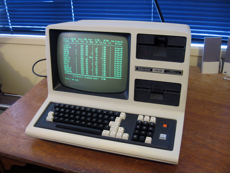
Figure 1. Two handsome floppy disk drives in my TRS-80 Model 4
Recently one of my TRS-80 Model 4 drives had been misbehaving. At one point I thought I’d fixed it, but the problem returned. Philip Avery and I managed to repair it eventually, but the solution involved more than just a simple alignment as described in our previous article. This fix required adjusting the stepper coupling, which appeared to have moved from its original position thereby throwing the drive alignment way out of whack.
What follows is an account of our diagnostic procedures and what we did. The drive was a TPI (Texas Peripherals) model used in the TRS-80 Model 4 but most full-height, belt-driven drives have similar mechanisms. Hopefully the explanation below will help others with similar problems.
Symptoms and initial observations
The drive concerned was the top drive in the TRS-80 Model 4 above. It could format and write disks just fine. It could also read its own written disks. However no other drive could read them! There was no interoperability.
We set up our workbench and started to look into the problem (Figure 2)
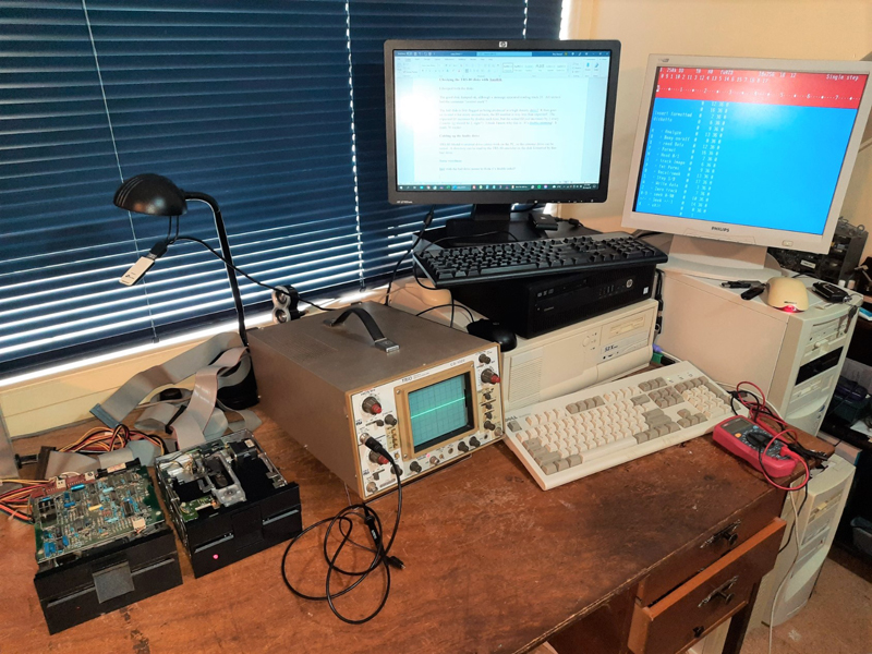
Figure 2. The workbench ready for action!
Using the alignment function on Dave Dunfield’s excellent ImageDisk program, we soon discovered the faulty drive was badly misaligned. We deduced this because:
- When the LS-DOS disk formatted on the faulty drive was read in a “known-good” drive, ImageDisk registered track 0 as track 2 and checksums weren’t matching up!? However, with a known-good MS-DOS disk (formatted in a known-good PC Drive) and a known-good LS-DOS disk (formatted in the other Model 4 drive), returning to track zero in ImageDisk showed we were indeed on track 0. Also with the latter, no errors were shown when we hovered over the track.
- When read in the faulty drive, known-good LS-DOS and MS-DOS disks showed a “?” in ImageDisk when set back to what was suppose to be track zero. When stepped forward two tracks, ImageDisk suddenly reported we were on track 0!? Conversely the LS-DOS disk formatted on the same (faulty) drive appeared normal in ImageDisk.
Conclusion: The drive was about two tracks out of alignment!
Why this misalignment happen and how to fix it
What would make the drive suddenly jump so far out of alignment? Acting on a hunch, Philip checked the screw on the “stepper motor coupling clamp" (Figure 3a and 3b). Hmm…This wasn't fully tight! Could this have caused the stepper assembly to jump a couple of tracks?
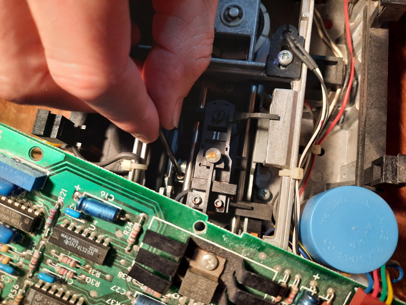
Figure 3a. Tightening the stepper motor coupling clamp
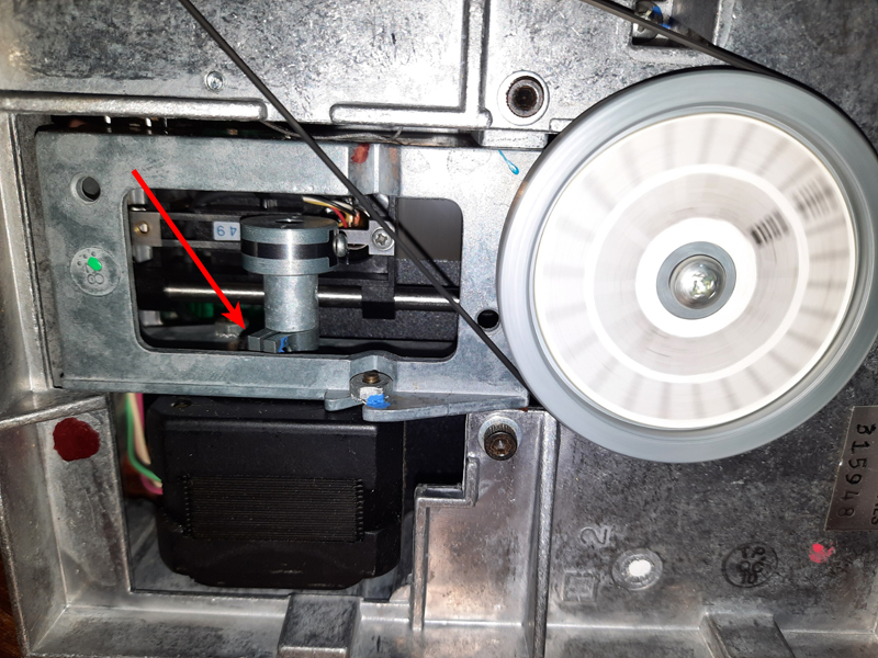
Figure 3b. The stepper motor coupling showing the position of the clamp screw (hidden in photo)
We tightened the stepper motor coupling clamp screw and at this point also serviced the drive with a drop of oil in the appropriate places (each end of stepper motor & also the clamping hub). We also cleaned and silicon-greased the rails.
Time to get aligning. Using a combination of oscilloscope, disks formatted in a known-good drives and ImageDisk to position the head over particular tracks, we managed to correct the offset of the drive (or so we thought) by turning the alignment screw. (Figure 4). ImageDisk was now reporting we were indeed on track 0 when we requested a return to track zero.
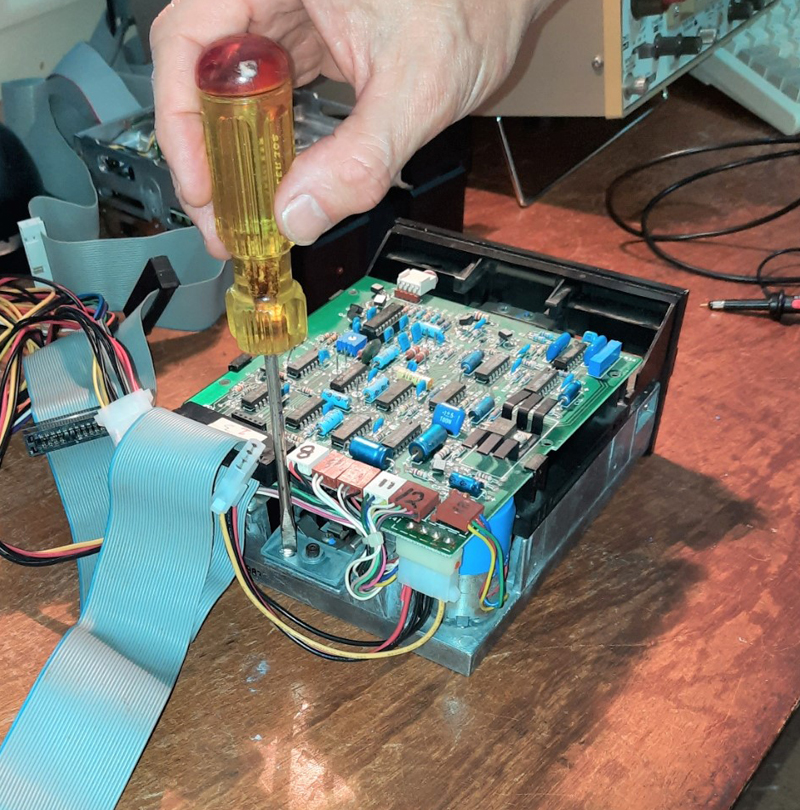
Figure 4. Aligning the heads with the alignment screw
However, the signal appeared faint on the scope at about 35mV?? (Figure 5). A good signal should be 250mv if not more. Our newly aligned drive gave the occasional successful read but only after several tries. We compared the same signal on a good drive using known-good PC and LS-DOS disks and found the faulty (now adjusted) drive’s signal over tracks was only about 1/7 the strength compared with the good drive, even at peak adjustment.
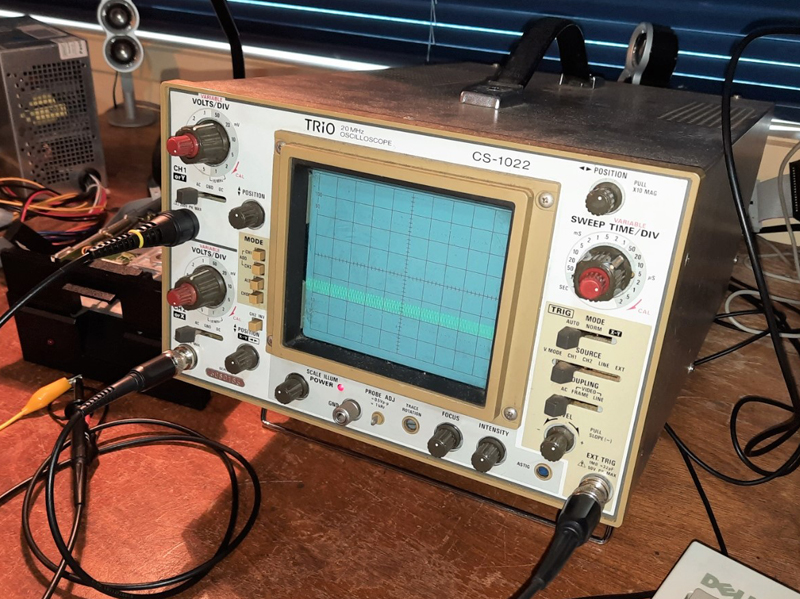
Figure 5. A weak signal, but the best we could get via the alignment screw (note: each divisions is 50mv)
Why couldn’t we get a stronger signal? Philip figured this may indeed be because the loose stepper coupling had slipped previously by two tracks & that the alignment screw cam might not give us the range of adjustment necessary to correct this.
We needed a coarse adjustment! To achieve this Philip loosened the (retightened) coupling clamp screw & adjusted the stepper coupling manually to move the head independently of the stepper motor (Figure 6).
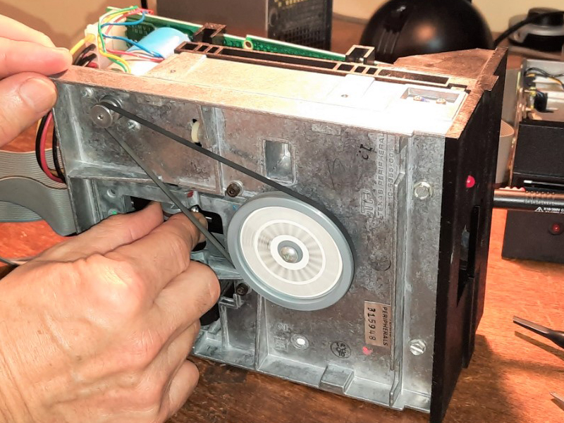
Figure 6. Turning the Stepper Motor Coupling
He merely turned the coupling making sure ImageDisk still displayed the track id that matched the selected track, then adjusted the coupling it until the signal on the scope was as strong as it could be.
After retightening the stepper coupling screw, we then fine-tuned with the adjustment screw cam to ensure we were getting the best signal we could. (Figure 7)
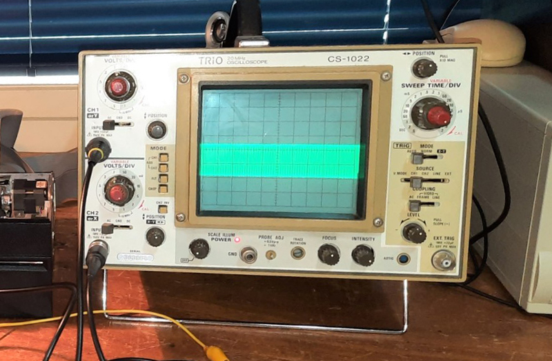
Figure 7. A strong signal after “coarse tuning” with the stepper coupling (note: each division in this case is 100mv)
Finally, we tightened everything up, connected our drive to the TRS-80 and exercised it thoroughly with floppy doctor. The drive now worked perfectly and with complete interoperability! (Figure 8).
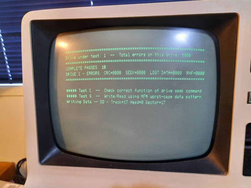
Figure 8. The drive passes all tests with flying colours including interoperability
Concluding thoughts
Maintaining these old drives without the specialist tools and training of the technicians of old, is somewhat of a black art! The importance of the correct placement of the stepper coupling in disk alignment, was bought home to me in this repair job. Check both screws (head band screw and clamp screw) on the stepper coupling are tight and if alignment seems impossible by the alignment screw alone, perhaps a loose stepper coupling is the culprit?
Terry Stewart (Tez) (and Philip Avery)
3rd September, 2022