Common System 80 Modifications
1.0 Introduction
2.0 Addition of two extra keys
3.0 Cassette gain control and a replay level
indicator
4.0 Lower-case
5.0 Switch for sound
6.0 Toggle switch for second cassette port
7.0 Memory upgrade
8.0 Joystick
9.0 Speedup kits
10.0 Hi-res graphics and colour
11.0 Internal Disk Interface
12.0 CP/M
13.0 Networking
14.0 Utility EPROMs
15.0 Miscellaneous
1. Introduction
It was common for early System 80's to undergo hardware modifications by their enthusiastic owners. Many of these were to make up for incompatibility problems with TRS-80 software. This was an important enough issue, for Dick Smith Electronics to issue special "Technical Bulletins" to owners with the modification instructions. Eventually, these sheets were included in later issues of the technical manual.
Modifications described in this web site but not in the manual are also available as a PDF downloadable supplement. (0.54MB). As the System 80 matured, most of these modifications became unnecessary because (thankfully) they were incorporated in the standard machine itself!
In some cases, modifications went beyond just TRS-80 Model 1 compatibility and fixing design flaws. Soon small New Zealand (and I'm sure Australian too) electronic companies were pushing boundaries with internal boards and modifications for color, hi-res graphics, disk interfaces, CP/M, speed-ups and even networking as shown in this ad from the September '83 issue of New Zealand Bits and Bytes.

First though, let's deal with the compulsory fixes to the early models....
2.0 Addition of two extra keys
The first System 80's were missing the CLEAR and TAB (forward arrow) key. This caused much consternation amongst owners as most machine language games required these very keys! Thankfully, the keyboard had space for them, and by replacing the right-hand shift key, it was (relatively) easy for the hobbyist to add them. I've reproduced the instructions here, from the Dick Smith System 80 Technical Manual (Version 2).
The System 80 keyboard as supplied at present does not provide the "forward arrow" (-->) or "CLEAR" keys present on the keyboard of the Tandy TRS-80 machine. This is generally not a major problem, as neither key is frequently used. However there are some existing TRS-80 programs where one or other is used.
Where such programs are written in BASIC, it usually a simple matter to modify the program so that is uses other keys. But this is generally not as easy to do with machine language or "System" programs.
As it happens, the addition of extra keys on the System 80 keyboard to provide the extra functions is electrically very simple. The keyswitches are arranged in a matrix which is software scanned, and the matrix positions which in the TRS-80 are occupied by both keys are currently vacant. So all that is needed are two additional pushbuttons or keyswitches, and four lengths of wire to connect them thus:
As you can see, the "forward arrow" key connects to the DK6 and AK6 scanning lines of the keyboard PCB, while the "CLEAR" key connects to the connects to the DK1 and AK6 lines.
But while this modification is electrically simple, it is not so easy mechanically. Ideally, perhaps, the switches would be mounted immediately to the right of the "BACKSPACE" key; but this would require cutting mounting holes in both the keyboard escutcheon and the metal mounting plate. The latter would mean removal of all the keyswitches, and few would be prepared to do this.
The exact approach used is a matter for the individual owner. Low-cost pushbuttons (like DSE Cat. No.S-ll02) could be used, and mounted in holes drilled in the panel escutcheon at convenient places.
Another possibility, and a rather neater one, is to fit the new keyswitches in place of the right-hand SHIFT key. This requires removal of the present double-width keytop, replacement of the present dummy spring unit alongside the shift keyswitch with a second switch, rewiring the existing switch and wiring of the new switch to the scanning matrix, and fitting the switches with suitably marked single-width keytops. This requires no cutting of the escutcheon, and produces quite a neat job.
3.0. Cassette gain control and a replay level indicator
This was another mod. common with the early machines...someway of controlling tape gain and monitoring it. It was only necessary in early models as later ones had a volume control and replay level indicator fitted, as they did the 2 missing keys above. Again, the text below is taken from the Dick Smith System 80 Technical Manual (Version 2).
The System-80 computer is fitted with an internal cassette tape deck, which provides no external user controls. The circuitry of the cassette deck and interface is such that, when correctly set up, most program tapes will load into the machine quite reliably. However pre-recorded tape cassettes vary quite widely in terms of both recorded level and signal waveform; this means that some tapes cannot be loaded satisfactorily without adjustment of replay gain.
As it happens there is an internal preset pot for adjustment of replay gain, fitted to the small PCB mounted under the internal cassette deck (VRl, at the front left-hand corner of the PCB). This pot may easily be removed and replaced by a normal l00k linear pot mounted on the rear of the case, to allow for external user adjustment. The new pot may be connected to the PCB via a single shielded cable, as shown:
The most convenient place to mount the new pot is on the right-hand side of the lower part of the System 80's case, alongside the cassette deck. There is just enough depth here to mount a standard-sized pot, which can be fitted with a small knob for convenient adjustment. To mount the pot you will have to drill a 4 or 5mm hole at the desired position, then carefully enlarge it using a hand reamer or similar until it is just large enough to accept the pot bush. Fix it with the usual washer and nut.
Note that it will be necessary to position the hole for the pot on the midline between the inner surface of the bottom of the case and the top of the moulding, to allow it to fit in place.
To allow convenient setting of optimum gain for different tapes, it is possible to provide the System 80 with a simple replay volume indicator. This can be done easily and at low cost by using the following circuit, which converts the existing "cassette recorder" pilot LED into a volume indicator:
As you can see, the additional circuitry required is quite simple and involves only two low-cost transistors, four resistors, a capacitor and a preset pot for calibration. Basically, the circuit detects the positive peaks of the replay signal and amplifies them to modulate the current drawn by the LED. The l0k pot may be set so that full LED brightness is achieved only when the positive peaks of the replay reach an amplitude sufficient to ensure reliable loading.
Rl0, the existing resistor in series with the LED, is mounted at the top right-hand corner of the keyboard PCB looking from the front of the machine. Removing this resistor provides two of the four connections required for the new circuitry. The earth connection can be made to the centre pin of the external cassette socket, at the rear of the machine, while the audio signal connection may be taken from the left-hand side of capacitor C24. This capacitor is at the extreme right-hand side of the interface PCB, just in front and to the right of the internal deck relay RLYl.
The two transistors and their associated wiring can easily be mounted on a small piece of utility PCB or similar. This can be attached to the rear of the keyboard PCB, immediately behind the original location of Rl0, supported by two short lengths of tinned copper wire used for the +5V and LED connections.
To set up the l0k preset pot, you ideally need an oscilloscope. This should be connected between either side of C24 and earth, to monitor the replay signal. Then insert a known good program tape in the cassette deck, set the deck for PLAY, and depress the Fl button. The replay gain control (VRl or the replacement l00k pot at the rear, if fitted) should then be adjusted to give a signal amplitude whose positive peaks are as close as possible to 3V. Note that this is not 3V peak to peak -- it is the amplitude of the positive peaks alone.
Now turn the l0k calibrating pot to maximum resistance, and slowly turn it back until the LED just reaches its maximum brightness. This completes your setting up.
Note that the LED indicator and replay volume control both operate in the "manual" cassette mode, with the Fl button depressed, as well as in auto mode. So manual mode may now be used to find the optimum gain setting for unknown tapes. Having done this, the tape can then be rewound and loaded normally via the CLOAD or SYSTEM commands.
The addition of an external gain control and simple LED level indicator generally make it possible to load just about all program tapes, both BASIC and machine language, using the System-80's internal deck. However it should be noted that there are still occasional tapes which will not load reliably at any gain setting, due to their severe waveform degradation. With such tapes, no simple techniques will allow normal loading; it is usually necessary to analyse the replay waveform with an oscilloscope, and process the signal in some suitable fashion to restore its integrity -- if this is possible.
4.0. Lower-case
 I'm
aware of two lower-case kits that came out for the early System 80's.
I'm
aware of two lower-case kits that came out for the early System 80's.
One kit was from Personal Micro Computers Inc., California, the folk selling the System 80 equivalent (PMC 80) in the U.S. The characters produced with this kit were clear, but lacked descenders which made g, j, p, q and y look a bit strange.
The lower case Mod that I'm most familiar with was the one developed and sold by Micro-80. This replaced the character generator chip with an EPROM and adds an extra VRAM IC. I installed this in my own machine. Even upper case letters were clearer than the original System 80 font, true descenders were present and there was even a set of playing cards symbols! It was an easy mod to fit, and was the first time I'd actually modified my own machine. What a thrill!
5.0. Sound
This was the second modification made to my own machine..by someone else though, not by me! Pre "blue-label" System 80 owners could not hear TRS 80 sound routines, even if a switch was fitted that "swapped" the two cassette ports. One reason was that bit 2 of port "FF" had to be set (i.e. B2=1) each time output data was fed to port FF to allow the data path through relay 2 contacts. This was solved by fitting a switch which "drove" relay two on permanently after loading the program.
Here is a drawing of the modification, taken from page 13, issue 19 (June 1981) of Micro-80. The diagram is designed to be used in conjunction with the Main Board Schematic in the Dick Smith System 80 Technical Manual.
6.0. Toggle switch for second cassette port
Even with the gain control and meter, problems could occur loading tapes, especially SYSTEM tapes. A modification swapping the two cassette ports was also popular on the System 80. My own machine was modified in this fashion. As before, the text below is taken from the Dick Smith System 80 Technical Manual (Version 2).
One of the advantages of the System 80 is the inbuilt cassette tape deck, which allows error-free loading of both BASIC and System (machine language) program tapes. Because the deck circuitry is designed to do this even when the recorded level of the tapes varies over a wide range, it is not provided with a user-accessible volume control. So there are normally fewer hassles in loading programs -- one less control to worry about.
However occasionally (Murphy's Law!) there are tapes whose recorded level is either too high or too low to load correctly with the internal deck's preset circuit.
With BASIC tapes there is no problem, because the CLOAD#-2 command can be used to load them via an external recorder with adjustable volume control. But this cannot normally be done with System tapes, as the SYSTEM command only loads tapes via the internal tape deck ("cassette No.1")
A similar problem occurs if you want to connect up to your System 80 a low-cost light pen designed for use with the TRS-80 (such as the X-3645). Such pens are designed to use the cassette recorder as a preamplifier; they plug into the recorder's MIC input. However there is no MIC input provided for the System 80's inbuilt cassette deck.
The answer is to use an external recorder, and plug the light pen into it. However the software normally supplied with the light pens is designed for a standard TRS-80, and accordingly it expects the pen to be connected to cassette No.1. Although the software can be modified, this can be tedious and time-consuming especially with machine-language programs.
A neater way of overcoming both of the above problems is to fit a simple switch to allow the internal cassette deck to be optionally disabled, and its functions transferred entirely to an external recorder. This effectively converts the System 80 cassette circuit into an exact replica of that in the TRS-80.
Basically, the System 80's cassette I/O circuit is exactly like that of the TRS-80 in that all data and control is transferred via I/O port address FF hex (255 decimal) . However because the System 80 has provision for two cassette recorders, additional circuitry has been added to allow connection of either one cassette or the other to the I/O circuitry.
The additional circuitry consists of a latch flipflop provided with decoding so that it effectively resides at a second I/O address FE hex (or 254 decimal) . Each cassette recorder circuit is controlled by a small relay, and the relay driver circuits are enabled by the two outputs (Q and Q-bar) of the latch flipflop. If hex l0 (decimal l6) is fed to I/O port FE, the latch flipflop is set, enabling the "cassette No.2" relay driver and allowing the external recorder to respond to normal tape communication via port FF. At the same time the "cassette No.1" relay driver is disabled, preventing that recorder from responding.
Conversely if hex 00 (decimal 0) is fed to I/O port FE, the latch flipflop is reset, disabling the "cassette No.2" driver and enabling that for cassette No.1". This is the normal circuit condition, with the internal cassette deck enabled.
To enable the external recorder to be used instead of the internal deck, without software changes, all that is required is the addition of a DPDT switch to allow optional disabling of the "cassette NO.l" relay driver, and connection of the other driver to the Q-bar latch output instead of the Q output. This makes the external recorder become "cassette No.1" as far as the software is concerned.
In schematic form the change looks like:
Mechanically the mod is easiest done by lifting one end of the series resistors R34 and R35 from the PCB.. Four wires can then be run to a small slider, toggle or pushbutton switch.
R34 and R35 are easy to find : they are on the top of the System 80' interface PCB at the rear and just to the front of pushbutton switch for 32/64 character line selection. The resistor for the external cassette drive, R34, is nearest the switch.
Probably the easiest place to fit the extra switch is on the lower back of the case, below the space between the 32/64 character button and the video output socket. Quite short wires can then be used to connect it to the resistors and PCB.
Don't forget the link between the switch contacts!

7.0 Memory Upgrade
 The
System 80 came with 16k of memory. Indeed, most cassette programs were
written assuming this amount but who wants 16k when you could get up to
48k, and hence be able to type more text in SCRIPSIT and load all those
monitor programs which let you do all kinds of things (like copy tapes
etc.).
The
System 80 came with 16k of memory. Indeed, most cassette programs were
written assuming this amount but who wants 16k when you could get up to
48k, and hence be able to type more text in SCRIPSIT and load all those
monitor programs which let you do all kinds of things (like copy tapes
etc.).
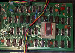
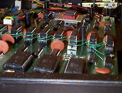
Memory expansion could be achieved by buying a standard expansion interface of course, but these were expensive. A quick and easy solution was to "piggy-back" new RAM chips on the existing ones, as shown in the photo opposite! This worked a treat and with careful soldering, owners could soon have a beast of a machine with 48k on-board (whoo-hoo!). This was how my own machine's memory was upgraded. Other methods are detailed here including one written in 2015!
8.0 Joystick
A joystick modification was serialised in the pages of Micro-80. If there is enough demand I'll scan it and put it up. I'm not sure if this was a popular option or not but I did once acquire a second-hand System 80 with one of these mods. It worked very well. Dick Smith Ltd. also sold a kit people could put together.
9.0 Speed Up Kits
Newer Z80 machines sold subsequent to the System 80 made the computer seem like a laggard. Kits were sold to turbocharge the System 80 into a faster machine. These instructions from New Zealand company John Gilbert & Company Ltd. are from such a package.
10.0 Hi-Res Graphics and Colour
There seem to be a number of boards produced that offered hi-res graphics and colour for the System 80 throughout the world. Dick Smith sourced a limited number of kits (just 200) for the System 80 and rumour has it that Lowe Electronics (U.K.) produced one for its equivalent in Europe, the Video Genie. Here in New Zealand there were two I know of, produced around 1983. One was called "The Graphcard" produced by Jenson and Parr of Christchurch. The other called "Chroma 80 II" was produced (or at least fitted) by John Gilbert and Co., Auckland.
11.0 Internal Disk Interface
System 80 expansion interfaces were costly, large and unwieldy. Although there wasn't a lot of spare room inside a System 80 John Gilbert and Co., Auckland (and possibly others) managed to produce boards which offered a disk interface but fitted inside the main unit. It's not clear whether or not these came with a printer card also?
12.0 CP/M
TRS-DOS, NEW-DOS and other TRS-80 disk operating systems were very powerful and there was a lot of good business software you could use with them. However despite these great programs nearly every System 80 owner really, really wanted to be able to run CP/M also, such was the dominance of CM/P in the 8-bit business market. The reason had little to do with logic. It was just that CP/M was such a standard if you DIDN'T have it you felt that your machine was less that a serious computer. After all, those smart-arse APPLE II owners could run CP/M so surely the System 80 should be dressed up for business as well.
Again, John Gilbert and Co. could deliver the goods, modifying the System 80 for CP/M. I've never seen a CP/M-capable System 80 so I'm not sure if the disk format was a special one or the same as some of the other CP/M machines like the Osborne 1. Apparently there was a switch which disabled the CP/M memory map allowed the machine to revert to it's normal state.
13.0 Networking
In the early 1980s in New Zealand, System 80s were very common in schools. They were cheaper than Apple IIs and had plenty of software. At least one high school (Waiopehu College, Levin, New Zealand) had a fleet of highly modified networked System 80s. Details of this innovative modification can be found here.
14. Utility EPROMS
Like the TRS-80 Model 1, the System 80 black label had 2k of ROM space spare between the end of BASIC and start of RAM. This could be filled with code from an EPROM plugged into a spare socket on the System 80 mainboard. Some companies provided EPROMS containing useful utilties. An example is this one from Z80 Programming, Melbourne. One particularly useful function on this utility package is the ability to load in machine code programs from cassette port #2. The EPROM code can be downloaded from here.
15.0 Miscellaneous
Other modifications included a 32/64 column "select in software feature (ala TRS80 model 1)". This provided the 32 column mode with the character double width, similar to that that the "video cut" button at the back provided. One or two sound amplifiers were also available ("Aftermarket" was one. - and it came with a volume control!).
Some hobbyists even put their favourite DOS in ROM. Check out ROMDOS/80.
Even in 2018, System 80 owners were building new interface boards! Read about the FreHDaptor here.